# Issues with CAN bus
**URL:** https://klipper.discourse.group/t/issues-with-can-bus/15771
**Category:** General Discussion
**Created:** [April 14, 2024, 1:39pm UTC](https://klipper.discourse.group/t/issues-with-can-bus/15771 "2024-04-14T13:39:19Z")
**Posts on this page:** 20
**Page:** 3
### Author:  [@hcet14](https://klipper.discourse.group/u/hcet14)
#### Post date: [April 16, 2024, 6:37pm UTC](https://klipper.discourse.group/t/issues-with-can-bus/15771/41 "2024-04-16T18:37:17Z")
@docgalaxyblock
Thanks for [Issues with CAN bus - #30 by docgalaxyblock](https://klipper.discourse.group/t/issues-with-can-bus/15771/30)
Nice “my Klipper Misc Docs”!
Quoting [DFU-UTIL](https://dfu-util.sourceforge.net/dfu-util.1.html)
What should I use to dump the firmware?
-Flashing a .dfu (special DfuSe format) file to the device:
$ dfu-util -D /path/to/dfuse-image.dfu
or
-Reading out 1 KB of flash starting at address 0x8000000:
$ dfu-util -a 0 -s 0x08000000:1024 -U newfile.bin
If last one, witch address and size should I use?
You might include the answer to my question in your “my Klipper Misc Docs”.
Thanks a bunch, hcet14
> [@DrumClock](#):
>
> I know that I don’t need a U2C converter for SKRat, I’m just trying the possibility of connecting CAN using the USB-C connector on the board and not the CAN connector.
That was hard to get! I absolutely understand TheFuzzyGiggler’s questions 😉
---
### Author:  [@docgalaxyblock](https://klipper.discourse.group/u/docgalaxyblock)
#### Post date: [April 16, 2024, 7:07pm UTC](https://klipper.discourse.group/t/issues-with-can-bus/15771/42 "2024-04-16T19:07:26Z")
> [@TheFuzzyGiggler](#):
>
> Page 9 shows the USB is just USB, not CAN (The output USB of the U2C adapter is CAN, which is weird as hell… What were they thinking on that one???)
> [@TheFuzzyGiggler](#):
>
> Also, Your U2C shouldn’t be showing up as an MCU. I think you’re trying to set it up like a CAN bridge and it doesn’t need to be. It’s a standalone device.
> [@TheFuzzyGiggler](#):
>
> and I’m not saying use the SKRat as the bridge, I’m saying you have your U2C set up as a CAN Bridge but it’s NOT. It’s a CAN Adapter.
>
> It should NOT be showing up in your MCUs.
There are multiple ways to setup an U2C.
I prefer (like @DrumClock wants to test it now) the way of using the klipper usbcan bridge fw since you use the same sourcecode on your usbcan adapter and the can node.
For the SKrat CAN bus on PD0/1 and PA11/12 are both valid options.
The first setting is for classic CAN\_H/L and the second one is for CAN\_RX/TX over a pysical usb cable. You can also connect the Octopus boards with both options
* * *
> [@TheFuzzyGiggler](#):
>
> In the case of the BigTreeTech U2C, this solution has no advantages over the candlelight firmware, since no freely usable pins are available on the board.
This is noted there since for can newbies it is the easier route cause in case of an klipper mcu protocol code change they do not need to reflash the can “adapter”.
---
### Author:  [@docgalaxyblock](https://klipper.discourse.group/u/docgalaxyblock)
#### Post date: [April 16, 2024, 7:15pm UTC](https://klipper.discourse.group/t/issues-with-can-bus/15771/43 "2024-04-16T19:15:30Z")
> [@DrumClock](#):
>
> The only thing I found out is that if the CAN bus stops working after a raspberry reboot, it helps to press the reset button on the SKRat board and restart the klipper. After that, the CAN bus starts again.
That is the U2C bridge and skrat can over usb setup? Interesting problem.
MainsailOS v1.3.2
To test it further can you please try a fresh MainsailOS and upload a printer.cfg with `kinematics: none` (and some other configs it will complain about)
then you can just add both mcus without anything else.
Try the U2C + one EBB.
Maybe I can find some time testing this next week (just U2C and EBB or U2C and SKR3 canoverusb) too
---
### Author:  [@docgalaxyblock](https://klipper.discourse.group/u/docgalaxyblock)
#### Post date: [April 16, 2024, 7:25pm UTC](https://klipper.discourse.group/t/issues-with-can-bus/15771/44 "2024-04-16T19:25:03Z")
> [@hcet14](#):
>
> -Flashing a .dfu (special DfuSe format) file to the device:
> $ dfu-util -D /path/to/dfuse-image.dfu
As it states that is flashing a device.
> [@hcet14](#):
>
> -Reading out 1 KB of flash starting at address 0x8000000:
> $ dfu-util -a 0 -s 0x08000000:1024 -U newfile.bin
yup that is dumping it
```bash
dfu-util -a 0 -U -s 0x08000000:0x040000 dump.bin
```
should be right.
Or use STM32CubeProgrammer and connect it in DFU mode - there you can “Read All” if you press on the dropdown arrow next to “Read”
Edit: STM32CubeProg can also be used to compare two dumped bins
---
### Author:  [@TheFuzzyGiggler](https://klipper.discourse.group/u/TheFuzzyGiggler)
#### Post date: [April 16, 2024, 7:53pm UTC](https://klipper.discourse.group/t/issues-with-can-bus/15771/45 "2024-04-16T19:53:45Z")
Okay, I get where this is confusing looking at BTT’s wording here…

That “CAN\_OUT\*” section about connecting to a USB where is horribly worded and backwards logic. USB is not CAN Bus and CAN Bus is not USB. You cannot have CAN Bus without some sort of CAN Transceiver.
To make this clear…
The BTT U2C schematic shows this…

The SN65HVD1050’s have **nothing** to do with USB, They’re CAN Bus transceivers.
> **[sn65hvd1050.pdf](https://www.ti.com/lit/ds/symlink/sn65hvd1050.pdf?ts=1713296374919&ref_url=https%253A%252F%252Fwww.google.com%252F)**
>
> 908.57 KB
To summarize, The USB “CAN\_OUT” on the BTT U2C is junk. Unless you cut open a USB cable and connect the D+ and D- wires to the CAN connection somewhere else, you will not get CAN out of that.
I have zero idea why they tried to implement that. My guess is they were throwing together a board and don’t know how to read datasheets.
* * *
Now that the U2C is out of the way.
The SKRat…
The SKRat USB connector is again… JUST a USB connector

It CANNOT handle CAN bus, it doesn’t DO CAN bus, It doesn’t even know what CAN Bus is.
HOWEVER… The CAN bus connector on the right hand side of the board…
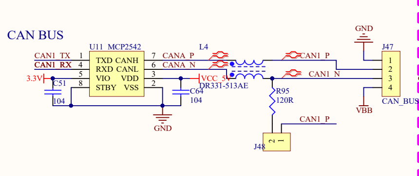
directly interfaces with an MCP2542
> **[MCP2542FD-4FD-MCP2542WFD-4WFD-Data-Sheet20005514B.pdf](https://ww1.microchip.com/downloads/en/DeviceDoc/MCP2542FD-4FD-MCP2542WFD-4WFD-Data-Sheet20005514B.pdf)**
>
> 1065.46 KB
Which is another CAN Bus transceiver.
Which brings us full circle back to…
> You cannot have CAN Bus without some sort of CAN Transceiver.
---
### Author:  [@TheFuzzyGiggler](https://klipper.discourse.group/u/TheFuzzyGiggler)
#### Post date: [April 16, 2024, 8:01pm UTC](https://klipper.discourse.group/t/issues-with-can-bus/15771/46 "2024-04-16T20:01:52Z")
I SEE WHAT THEY DID! Or tried to do!
I was _RIGHT_, They don’t know how to read data sheets!

[https://www.st.com/resource/en/datasheet/stm32f072c8.pdf](https://www.st.com/resource/en/datasheet/stm32f072c8.pdf)
Page 41.
Notice what’s omitted from the original pic, The top of the table where it says “ALTERNATIVE FUNCTIONS”
STM32 has pin configurations, in other words, you can change the function of a pin based on your need. Maybe you don’t need CAN Bus… Then that Pin works as USB, or a timer, or a comparator or whatever based on WHAT YOU CONFIGURE IT AS IN THE FIRMWARE.
BTT read this and thought “Oh, It can do **ALL OF THESE AT ONCE** ”
That is **NOT. TRUE.**
That’s why they did the confusing thing of putting CANBus on a USB connector, because they misread the datasheet.
---
### Author:  [@DrumClock](https://klipper.discourse.group/u/DrumClock)
#### Post date: [April 16, 2024, 8:04pm UTC](https://klipper.discourse.group/t/issues-with-can-bus/15771/47 "2024-04-16T20:04:20Z")
But the STM32G0B1xx chip can do CAN function on PA11/12, look at its datasheet (I sent it above)
> [@DrumClock](#):
>
> STM32G0B1xxx
>
> 
---
### Author:  [@TheFuzzyGiggler](https://klipper.discourse.group/u/TheFuzzyGiggler)
#### Post date: [April 16, 2024, 8:06pm UTC](https://klipper.discourse.group/t/issues-with-can-bus/15771/48 "2024-04-16T20:06:46Z")
> [@DrumClock](#):
>
> But the STM32G0B1xx chip can do CAN function on PA10/11
I agree with you 100000000000000000000000000000000000000%
But it CANNOT do CAN Bus and USB at the same time on the same pins.
Therefore it’s extremely stupid and confusing for them to run CAN Bus over a USB connector.
The SKRat CANNOT do CAN Bus on the USB connection as you are doing it.
You’re focusing on the U2C, ignore the U2C.
The SKRat does not function as you’ve connected it.
You HAVE to use the CAN Bus connector on the right hand side.
---
### Author:  [@docgalaxyblock](https://klipper.discourse.group/u/docgalaxyblock)
#### Post date: [April 16, 2024, 8:08pm UTC](https://klipper.discourse.group/t/issues-with-can-bus/15771/49 "2024-04-16T20:08:08Z")
@TheFuzzyGiggler Can please understand the difference between CAN\_RX/TX and CAN\_H/L ‼ Otherwise you are lost…
Look how the stm32 is wired to the transreceivers - it talks “serial can” () CAN\_RX/TX to the transreceiver - the same signal gets transported by the physical ❗ USB cable to the SKrat
> [@TheFuzzyGiggler](#):
>
> 
As this part of the schematics show it is CAN\_RX/TX
CAN\_H/L is only available at the Molex Minifit JR and screw terminal
---
### Author:  [@docgalaxyblock](https://klipper.discourse.group/u/docgalaxyblock)
#### Post date: [April 16, 2024, 8:13pm UTC](https://klipper.discourse.group/t/issues-with-can-bus/15771/50 "2024-04-16T20:13:29Z")
> [@TheFuzzyGiggler](#):
>
> Therefore it’s extremely stupid and confusing for them to run CAN Bus over a USB connector.
I agree that their choice of USB as the pysical cable is not great.
Newbies think it is USB and connect other boards there and then wonder why it is not working
Also to you: **get the difference between CAN\_RX/TX and CAN\_H/L**
---
### Author:  [@TheFuzzyGiggler](https://klipper.discourse.group/u/TheFuzzyGiggler)
#### Post date: [April 16, 2024, 8:16pm UTC](https://klipper.discourse.group/t/issues-with-can-bus/15771/51 "2024-04-16T20:16:20Z")
You’re both focused on the U2C.
The SKRAT has NO CAN TRANSCEIVER on the USB CONNECTOR.
Therefore it CANNOT do CAN Bus via the connector in the way that @DrumClock is connecting it.
Just because a Microcontroller has the CAN Protocol built it, it HAS to have a transceiver to drive the CAN lines per the CAN standard.
Lets recap:
- I agree the STM32 chip on both the SKRat and the U2C support to the CAN Bus protocol.
- I agree that, althought its weird, the U2C supports CAN bus over that USB A connector
What I DON’T agree with, Is that you can use the SKRats USB connector as CAN Bus.
@DrumClock - Yes, The STM32G0B1 supports CAN on PA11/PA12.
On the SKRat

CAN RX/TX is connected to PD1/PD0.
PA11/PD12 are configured for USB.
PA12/PA11 do not have a CAN transceiver, PD1/PD0 do.


Therefore, to use CAN Bus on the SKRat in the way your wiring picture is up top doesn’t work. You HAVE to connect it like you’ve connected the EBB boards using the CAN connector on the right hand side of the board.
Edit:
From the STM32G0B1 datasheet, PD0 and PD1 are FD Can pins, and the MCP2542 is an FD Can transceiver. That’s the pin setup for the SKRat.

---
### Author:  [@docgalaxyblock](https://klipper.discourse.group/u/docgalaxyblock)
#### Post date: [April 16, 2024, 8:23pm UTC](https://klipper.discourse.group/t/issues-with-can-bus/15771/52 "2024-04-16T20:23:56Z")
> [@TheFuzzyGiggler](#):
>
> You’re both focused on the U2C.
No the same is valid for the SKrat.
> [@TheFuzzyGiggler](#):
>
> The SKRAT has NO CAN TRANSCEIVER on the USB CONNECTOR.
>
> Therefore it CANNOT do CAN Bus via the connector in the way that @DrumClock is connecting it.
That is correct and it does not need a transreciver if U2C PA11/12 and SKrat PA11/12 are connected.
Both STM32G0B1 are talking CAN\_RX/TX with each over.
You can configure them to talk either D+/D- or CAN\_RX/TX on both ends over the same cable.
> [@TheFuzzyGiggler](#):
>
> Just because a Microcontroller has the CAN Protocol built it, it HAS to have a transceiver to drive the CAN lines per the CAN standard.
Year that is CAN\_H/L and they are not using this over the USB.
---
### Author:  [@TheFuzzyGiggler](https://klipper.discourse.group/u/TheFuzzyGiggler)
#### Post date: [April 16, 2024, 8:33pm UTC](https://klipper.discourse.group/t/issues-with-can-bus/15771/53 "2024-04-16T20:33:28Z")
???
You have to have a CAN Transceiver as the physical layer and signal conversion/conditioning.
The Microcontroller only sends out digital signaling but CAN Bus is differential signaling, CAN Bus requires specific termination and line impedance requirements and biggest of all, They’re wildly different voltages.

CAN RX/TX is just the serial protocol, It always requires a transceiver.
Which the SKRat has, it’s just on different pins than the USB connector.
Edit: Unless you’re saying the U2C and SKRat are trying to communicate with each other via their CAN Bus RX/TX lines? Maybe that’s where I’m getting lost at and that’s janky as hell.
---
### Author:  [@docgalaxyblock](https://klipper.discourse.group/u/docgalaxyblock)
#### Post date: [April 16, 2024, 8:37pm UTC](https://klipper.discourse.group/t/issues-with-can-bus/15771/54 "2024-04-16T20:37:38Z")
> [@TheFuzzyGiggler](#):
>
> The Microcontroller only sends out digital signaling
> [@TheFuzzyGiggler](#):
>
> CAN RX/TX is just the serial protocol
100% correct and this serial data gets created by the u2cs stm32, transfered over a three pin cable and received by the stm32 of the SKrat
---
### Author:  [@docgalaxyblock](https://klipper.discourse.group/u/docgalaxyblock)
#### Post date: [April 16, 2024, 8:38pm UTC](https://klipper.discourse.group/t/issues-with-can-bus/15771/55 "2024-04-16T20:38:13Z")
> [@TheFuzzyGiggler](#):
>
> Unless you’re saying the U2C and SKRat are trying to communicate with each other via their CAN Bus RX/TX lines?
You got it now 🥳
I need to get some sleep for tomorrows work now.
---
### Author:  [@TheFuzzyGiggler](https://klipper.discourse.group/u/TheFuzzyGiggler)
#### Post date: [April 16, 2024, 8:44pm UTC](https://klipper.discourse.group/t/issues-with-can-bus/15771/56 "2024-04-16T20:44:48Z")
… How is it handling the dominant/recessive bit issues and bus contention?
99% sure that’s not how that is meant to work, logically or via STM32 documentation.
But oh well. I give up on this one.
Carry on.
Edit: I guess the consensus is that it CAN (see what I did there?) be done, but there is zero noise immunity and it’s really finicky and requires ultra short wiring and fast diodes.
> **[siemens\_AP2921.pdf](https://www.mikrocontroller.net/attachment/28831/siemens_AP2921.pdf)**
>
> 19.83 KB
No wonder people have issues with BTT boards and CAN Bus in all the forums.
---
### Author:  [@DrumClock](https://klipper.discourse.group/u/DrumClock)
#### Post date: [April 17, 2024, 4:41am UTC](https://klipper.discourse.group/t/issues-with-can-bus/15771/57 "2024-04-17T04:41:52Z")
@TheFuzzyGiggler
1. between the CAN bus in U2C and the STM32 chip on the SKRat board is the SN65HVD1050 transceiver
2. on SKRat, CAN communication is set on pins PA11/12
3. CAN communication is functional via the U2C converter and SKRat using a “USB” cable. Unfortunately, only until the raspberry “rebbot” is implemented.
4. Then just reset the SKRat board with the button and the CAN works again.
I hope you already understood it, or buy U2C, SKRat and EBB and you can see for yourself.
---
### Author:  [@koconnor](https://klipper.discourse.group/u/koconnor)
#### Post date: [April 17, 2024, 3:53pm UTC](https://klipper.discourse.group/t/issues-with-can-bus/15771/58 "2024-04-17T15:53:43Z")
> [@DrumClock](#):
>
> CAN communication is functional via the U2C converter and SKRat using a “USB” cable. Unfortunately, only until the raspberry “rebbot” is implemented.
Well, I would call that not functional. I expect it will be unstable in that configuration, even beyond reboots.
I recommend returning to a more standard setup. If you want to use the CAN protocol, then deploy CAN transceivers on all the target devices. If you want to use USB wiring, then wire them to USB ports. I would definitely avoid running any CAN signalling over USB wires.
So, if you want to run a USB wire to the SKRat then use a USB wire directly to the RPi and use standard USB communication over those wires.
You definitely do not want to run CAN RX/TX over long lines. It is definitely not valid to wire multiple devices to the same CAN RX/TX wires (these wires are not a “bus” - they are only point-to-point and intended for short distances).
Hope that helps,
-Kevin
---
### Author:  [@DrumClock](https://klipper.discourse.group/u/DrumClock)
#### Post date: [April 17, 2024, 5:23pm UTC](https://klipper.discourse.group/t/issues-with-can-bus/15771/59 "2024-04-17T17:23:23Z")
Hi, the fact that the “Chinese” used a USB cable for CAN bus transmission is their “fast needle”.
However, this does not change the fact that when using the U2C converter, the CAN bus is brought via this cable in the same way through the SN65HVD1050PR converter to the STM32G0B1xx pins as it is with the EBB42.
So I don’t see a single reason why it shouldn’t work if I set CAN communication via PA11/PA12 (USB-C connector) in “make menuconfig” for SKRat.
The only thing in the way (and it’s different than the EBB42) is the USBLC6-2SC6 diode array to protect the USB-C connector.
@koconnor
I wonder if this diode array can cause CAN bus protocols to malfunction?
USBLC6-2SC6

---
### Author:  [@mykepredko](https://klipper.discourse.group/u/mykepredko)
#### Post date: [April 17, 2024, 5:43pm UTC](https://klipper.discourse.group/t/issues-with-can-bus/15771/60 "2024-04-17T17:43:04Z")
Can I ask a question as I’m curious about the psychology of what’s going on here.
The background is:
- You do not have a stable CAN connection. You claim that it works initially but it does not survive host reset/power cycle.
- @TheFuzzyGiggler has tried to explain at length that there is a problem with your understanding of how CAN and USB are wired on the U2C and main controller board.
- @hcet has expressed concerns about how you are doing things.
- I told you that the wiring wasn’t correct.
- The creator of Klipper, @koconnor has called your method “not functional”.
My question is: at what point will you accept that your approach is wrong?
[Previous page](https://klipper.discourse.group/t/issues-with-can-bus/15771.md?page=2)
[Next page](https://klipper.discourse.group/t/issues-with-can-bus/15771.md?page=4)