Semi-bowden extrusion with force control

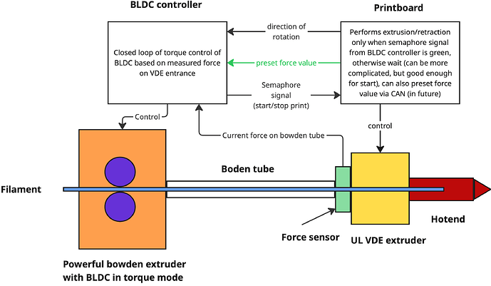
I am thinking about this setup. On the side of printhead we have very light VDE-100 extruder (extruder A) with weak nema-14 pancake, (all together, extruder + stepper, is like 50 grams or less). This pancake does not enough of torque to extrude, but construction of VDE is good enough to act as filament gate with controllable pass through, if we have force from somewhere else. On other side of the Bowden tube (on the frame) we have powerful extruder B (doesn’t matter which one, as weight is not an issue there). Where bowden tube connects to the extruder A, we have force measurement point where we measure force in the bowden tube with force sensing resistor, for example. So, effectively, extruder B provides us with force, and extruder A acts like controllable gate. Then extrusion works like this:

we want to extrude, we control extruder B to push enough, that force will reach some target value (so, we preloaded extruder A), then by extruder A we actually extrude (in reality, it does not extrude but allow given amount of filament to path, with force provided by B), at the same time we still control force to be at target value by pushing filament by B. Once we stop, we can gradually/immediately release force, or keep system, preloaded. When we need to retract, we reverse stepper B, and pull filament till we reach target retract force value, then we “retract” by stepper A (while pull by B still maintains target force). So, in this system extruder A is kind of main extruder, which is responsible for accuracy, but force is provided by extruder B, which can be as heavy as we want.

So, how complex this will be to implement?
In some sense, it is bowden pressure advance system, but

  1. with exact measurement of force/presure in the bowden tube on the hotend side (or both sides, it might have some value).

  2. with controllable gate on hotend.

In fact, we can simplify, extruder B with BLDC can be controlled by separate controller, all it need is direction in which force should be maintained.

So, for klipper then, it is simplified:

  1. it signals (for example on of pins of MCU) direction of extrusion.

  2. Waits till force from sensor will reach target value (or at least 5% bellow target value, for example), then extrude/retract with extruder A.

In fact, we can simplify even more, external controller, which controls B, and anyway reads force from sensors and know target value, can signal good-to-go to klipper. Then it is even simpler:

Klippers signals to external controller direction of extrusion, but, before extruding, waits till get green signal from that controller. How difficult to add this change?

I’m not on the official team but until we hear from them here are my thoughts.

Building a push/pull device with an Arduino or Pi would be simple enough. It could be open loop (specified wait time) or built to send a ready signal. A simple spring concentric with the PTFE tube and a linear position sensor would be sufficient to estimate the strand tension/compression. I do think that the time it will take to reverse is much longer than you realize. Adding, say, 800ms (400 each direction) to every retraction is going to negate any speed gains you realize with a lighter toolhead. Also oozing during the wait might be sufficient to make the retraction useless.

You would also need added functionality in your slicer or write a script to parse your g-code and insert custom commands prior to any retractions.

AFAIK Klipper doesn’t currently “know” when a retraction is coming and without a custom g-code to call a macro to pause and wait for either a preset time or until the ready signal arrives you’re out of luck. @koconnor has stated that code changes for features of this type won’t be considered unless a population of 100 users are interested.

You can think of it as bowden with precise pressure advance control and precise dosage on hotend. So, it can not be slower than usual bowden. But might be tad faster. And, unlike usual Bowden, it will be precise.

In principle, if BLDC in large extruder controlled via B-G431B-ESC1, which supports CAN, then we can even set particular pressure targets from klipper. (for example, depending on filament material or something else).

And when it comes to changes, I have no problem to implement them in klipper myself, I just want to hear if there are some expected issues under the water I am missing. From the very first look, it is simple state-machine. Extrusion G-code command comes, we set polarity bit, and continue once green-lighted, When extrusion does not change sign, green light is granted to be there right now, if it changes sign, then yes, there is short delay, till we get green light. But then again, it is all matter of tuning, and matter of hardware (with pancake stepper I am aiming at, we don’t need full target pressure to arrive, stepper with VED can deliver almost enough itself, from what I see). Plus, again, large extruder uses BLDC, and has faster response time, higher RPMs, and might have higher torques (here we don’t care about weight and size), so it must be able to reverse pressure polarity somehow faster, than stepper in usual bowden setup.

And, with this setup we have chance to limit weight of full printhead (extruder + hotend, something like Rapido) to 100-120g (assuming CPAP cooling). In this case we can deliver Galileo-2 force with fraction of moving weight.

If you want my “2 cents”, it certainly sounds like it could be useful functionality. Some random comments:

  • A challenge is likely going to be getting hardware widely available. It’s a bit of a “chicken and egg” situation - it’s hard to write the software without known hardware to work on, but hardware manufacturers are unlikely to widely manufacture devices without software support..
  • If one did want to set something like this up, I’d recommend hardware with at least 10mm or so of “buffer” between the two motors. You likely don’t want the two motors directly attached to a rigid ptfe tube where they could be “fighting” each other.
  • For what it is worth, if you’re planning on an implementation that tries to quickly react to “force measurements” then I’d guess that would be challenging to implement in Klipper. Everything in Klipper is designed to be scheduled well in advance. As an alternative to direct responsiveness, one could look to schedule filament movement on both motors and use the “force sensor” to constantly alter the ratio of motor movement for the two motors. Said another way, instead of trying to react to measurements, try to predict the measurements in advance so that motor movements can be scheduled.

Again, just some random thoughts,
-Kevin

Something like this:

Bowden extruder: Some really powerful and fast BLDC, weight does not matter. Preferably belted extrusion.
BLDC controller: B-G431B-ESC1 (has CAN bus support, which allow us to enable communication with printboard in future)
Force sensor: fixture on the base of (1, 2 or 4) KFGS-2-120-C1-11.
UL(ultralight) VDE: low tilt angle for blades, very weak motor (as planning this around pieso which cost like 1K is pointless, I am going to investigate what I can do with something like 1804 motors).

You didn’t get it. Buffer is something which kills whole idea :slight_smile:

Buffer you need when you have typical buffered setup when to extruders work in typical push-pull setup. This is something else :slight_smile:

Whole concept here is to remove need to worry for printing scheduler about large bowden extruder. It has separate controller which controls it on the base of target force, extrusion polarity and force measurement. Only communication with print scheduler is extrusion direction and, ideally, semaphore signal from bowden controller to print scheduler.

First move your force sensor to the other end of the boden (move the mass to where it doesn’t matter).
Second add spring elements to both the boden AND the filament.

I feel you are underestimating the amount of elasticity in the system. It could work but I feel the time required to “adjust” the filament force is going to end up slowing things down.

Another consideration. The force created by the “big” motor must not be so large that it overwhelms the small one. Unless you use a high reduction worm gear train this force has to be smaller than the maximum force the small motor can generate. This limits the total filament force into the melt zone to around 1.75 the small motor force.

I have seen extruders with worm gear drives but AFAIK the backlash was so bad that that design was abandoned.

Hi. I actually tried to implement that concept a while ago, but instead of bldc motor, i used a regular bmg style extruder, and i used an arduino board to control it.

Unfortunately, i was not able to implement/tune the control loop in a way to avoid the oscillations.
But I still think that the concept is interesting, and with more work put into that may work pretty well.

Interesting proposal, but Semi-bowden extrusion with force control - #5 by koconnor

Seems like a brain crushing thing to implement it in Klipper, but I’m no programmer!