Fill out above information andin all cases attach yourklippy.logfile (use zip to compress it, if too big). Pasting yourprinter.cfgis not needed Be sure to check our “Knowledge Base” Category first. Most relevant items, e.g. error messages, are covered there
Describe your issue:
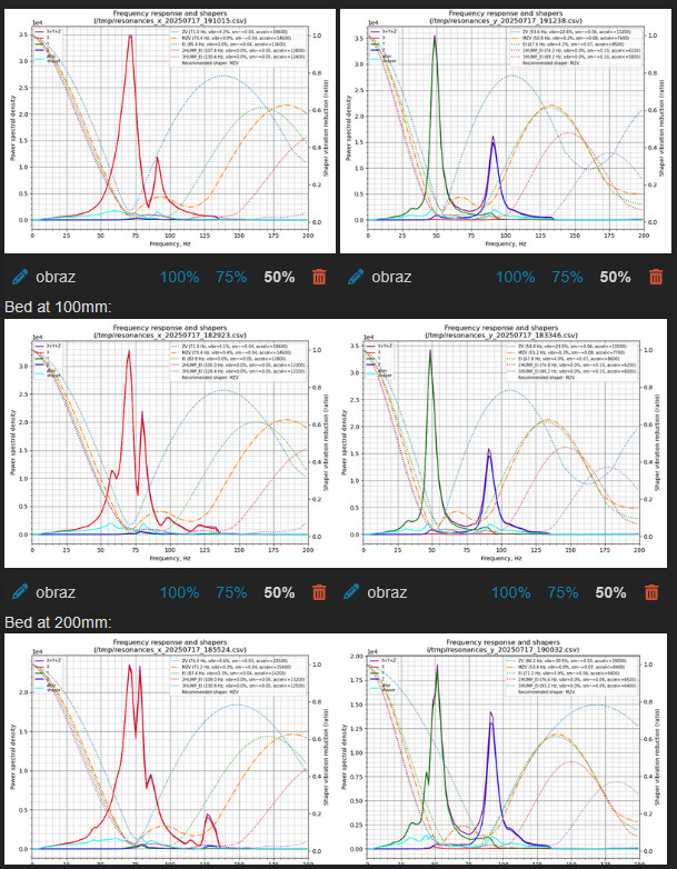
Hi, just wanted to check if someone would help me interpret these input shaper graphs for my machine.
I wanted to hit accels of above 10k for printing. it is totally possible for the X axis (~20k accels) but still having problems with the Y.
I really dont know how to interpret the 90hz Z axis spike on this one.
Important note is that when i placed the accelerometer on one of the Y carriages the Z spike disappears. So its probably only on the X beam.
added diagonal printed frame stiffeners to every side;
added horizontal 2020 beams in the middle of Y walls;
tightened every screw in the system;
today ill clean the linear rails again to check for change.
If someone has any ideas please share even if you are not sure. I’ll be happy to brainstorm with ya all.
There is no such thing as a free lunch, and the general rule of thumb is:
More aggressive shaping = more smoothing
Lower target frequency = more smoothing
More acceleration = more smoothing
With 1e4 your PSD is pretty low anyway, so you need to empirically test what is the real world impact:
Use MZV and live with potentially some smoothing
Use ZV and live with some remaining resonance
Try to get rid of the first peak by mechanical measures, but this is very difficult and only trial and error as you cannot determine the source of the resonance from the graph.
Even if you think that X is ok it is helpful to post both input shaper graphs.
The Z spike here might result from a twisting print head, depending on where the accelerometer is attached to or maybe a running fan.
However you have three different documents in this shaper graph calculation that might introduce different issues each, although they are all created on the same day.
So for your next IS measuring session please delete all old logs or move them to a different folder upfront.
How big is your printable area?
The spike at around 47 Hz is a bit low though in almost perfect shape…
Did you check your printers belt tension? How did you do that?
The system decided to ban my account for using one frasal about throwing stuff at the wall and seeing what sticks… and it seems to be forever. whatever
I initially wanted to post both of the graphs but couldnt because of one image per post for new users.
I’ll upload both graphs when ill be back from work. The accelerometer is mounted on the hotend fan casing.
My printable area is 220mm X 220mm X 320mm.
I checked the vibrations with different belt tensions using spectroid. The best results seem to be when they are tighter, but that introduces a lot of different problems. The Z spike on 80-90hz doesnt seem to change when i do it though. The belt tension only changes the steepness of the first spike.
I think it may as well be because my motion system is 3d printed with PETG-CF from BambuLab (the mercury one system) and it may be the weakest link in the frame/system
i know that the image is in low res but again cannot post more than one at a time
The conclusion is the lower the bed the more inconsistent the resonance but its power drops, maybe some lever effect. When it is at the top of the frame it exerts a lot more force on the whole frame
I’ll clean and oil the rails and test again.
Edit: When the bed is down the vibrations become so irrelevant that testing in this position might be worthless
Yup, exactly.
It was a printer of Theseus, upgraded during two years,my first printer. Now only the frame is original. Maybe you have some ender 5 specific tips about frame stiffness?
Have a question, does anyone know what is better, or in which way?
I currently have installed two horizontal 2020 beams in the middle of my Y axis walls.
Would it be better to install them higher, near the actual motion system?