
no I’m not trying to connect to EBB 42! I have EBB SB2240 board! but Eddie is connected directly to MANTA MP8 v2 in i2c connector with long cable about 2m
The Manta board already has pull-up resistors on the 10kOhm bus! If I add another 4.7KOhm, it will be too much. On the contrary, I need to reduce the resistor rating on the board! But this is very difficult and after changing this port, you will not be able to turn on anything else because it will be configured for this cable length!
there is still a problem! when Eddy is power on
then Knomi loses wi-fi) but Eddy even with such a bad schedule scans the table, but not always) an error appears shutdown: i2c timeout


Apologies, I misread the CAN toolhead controller when I did a quick scan of the first post in the thread.
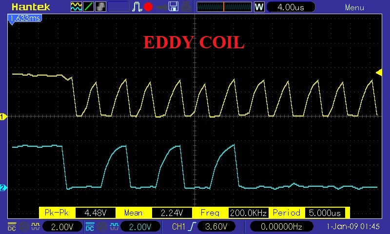
Thanx for the 'scope images at both ends - the way you have things wired, it will never be reliable.
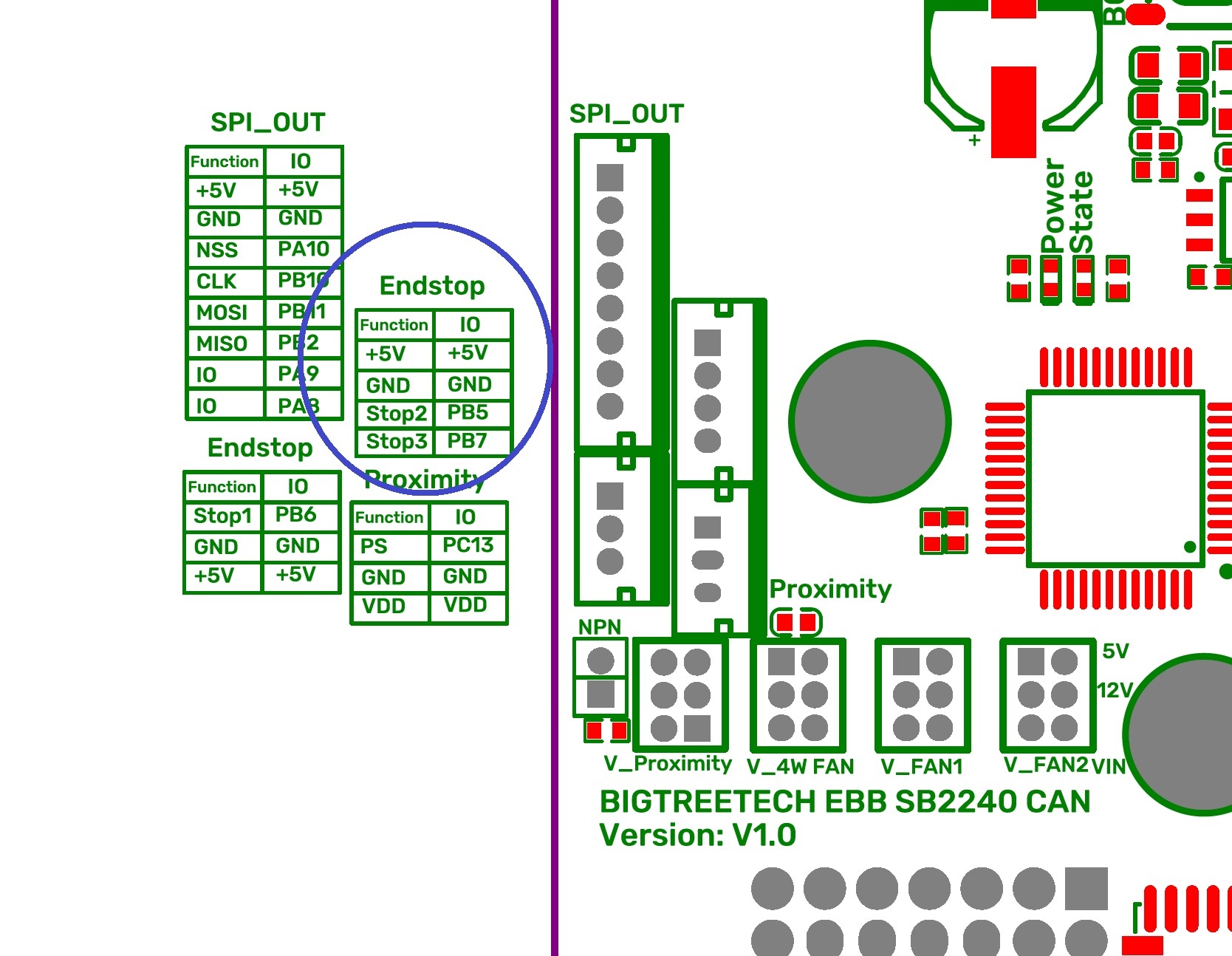
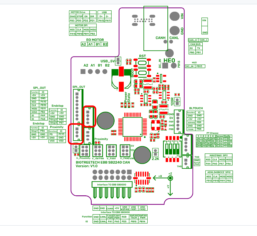
Now, I don’t know how you have your SB 2240 set up, but if you have header P19 open (Endstops 2 & 3) on the board:

Then you should be able to wire it as shown in the Eddy Coils User Manual for the EBB42:

Then, in your printer.cfg set up your I2C bus for software SCL/SDA pins as described in the Klipper Configuration page:
[probe_eddy_current my_eddy_probe]
sensor_type: ldc1612
#   The sensor chip used to perform eddy current measurements. This
#   parameter must be provided and must be set to ldc1612.
#intb_pin:
#   MCU gpio pin connected to the ldc1612 sensor's INTB pin (if
#   available). The default is to not use the INTB pin.
#z_offset:
#   The nominal distance (in mm) between the nozzle and bed that a
#   probing attempt should stop at. This parameter must be provided.
#i2c_address:
#i2c_mcu:
#i2c_bus:
#i2c_software_scl_pin:
#i2c_software_sda_pin:
#i2c_speed:
#   The i2c settings for the sensor chip. See the "common I2C
#   settings" section for a description of the above parameters.
#x_offset:
#y_offset:
#speed:
#lift_speed:
#samples:
#sample_retract_dist:
#samples_result:
#samples_tolerance:
#samples_tolerance_retries:
#   See the "probe" section for information on these parameters.
I’d give it an 80%+ chance of working - sorry, I can’t verify it here.
If you’re already using P19, then I suggest you look at P5 (BLTouch Connector) but you may want to add a 4k7 resistor to the SERVOS line.
Is that with or without the ferrite beads in place? If they’re in place, I’d be curious to see what happens with the KNOMI is removed (I use a couple of them on my printers and they’re rock solid for me).
Anyway, why don’t you try the connection I’ve outlined above (which is really what I meant in my previous post)?
Good luck!
if i understood you correctly! then you suggest
getting rid of the long wire and connecting Eddy coil directly to the EBB2240 board! i thought about it too! but i don’t understand which #i2c_bus: to choose in the settings! pin PB5 does not support the function i2c
Here are the possible options:
MCU ‘sb2240’ config: ADC_MAX=4095
BUS_PINS_i2c1_PA9_PA10=PA9,PA10 BUS_PINS_i2c1_PB6_PB7=PB6,PB7 BUS_PINS_i2c1_PB8_PB9=PB8,PB9 BUS_PINS_i2c2_PB10_PB11=PB10,PB11 BUS_PINS_i2c2_PB13_PB14=PB13,PB14
BUS_PINS_i2c3_PB3_PB4=PB3,PB4 BUS_PINS_i2c3_PC0_PC1=PC0,PC1

I think it’s possible to use this Bus pins PB6,PB7
and X axis assign a limit switch pins PB5
or else
use BLTouch Connector
What do you think, will this work?
Actually, I’m working on a new board design with the STM32G0B1 (the same as in the EBB SB2240) and PB6/PB7 would be my recommendation BUT they will have to straddle two connectors that could be awkward to wire to:
I suggested Endstop2/Endstop3 as it would be easier to wire and, as I said in my previous post, you would use i2c_software_scl_pin and i2c_software_sda_pin.
Now, I’ve just taken a look around at what other people are doing and it seems like you get the best results using a hardware I2C port so, if you wanted to use a hardware I2C then PB6/PB7 would be the way to go (which means combining between the two connectors).
I think the best way to wire it would be to use P10 for 5V/GND/Stop1 (PB6 - SCL) and Pin 3 on P19 for Stop2 (PB7 - SDA). Not completely neat but I’ve seen worse as there’s no need for soldering, you just need to make up the cable or modify the one that came with the Eddy Coil (I would probably choose the latter).
PB6/PB7 are the default I2C1 port/bus pins in Klipper.
Once you wire in the Eddy Coil, look at the I2C signals on your 'scope (and show here) to see how the signal has changed (and hopefully improved significantly).
good afternoon) I agree this option will look strange) when wires from one sensor go to two connectors))) but in our case this is the best solution) ok! I’ll go implement our idea) a little later I’ll send a photo and the measurement results!
great, that’s what I’ll do
stop!!! we forgot that there should be pull-up resistors on the wires SCL/SDA!!!
because on Eddy coil is not pull-up resistors in the circuit!!!
what to do??? try without them??? or is it possible to pull them up programmatically? but how to do it?
these 1.5mm connectors are a nightmare to crimp! I soldered them) if I can’t do the pull-up programmatically, I can install resistors on these wires!

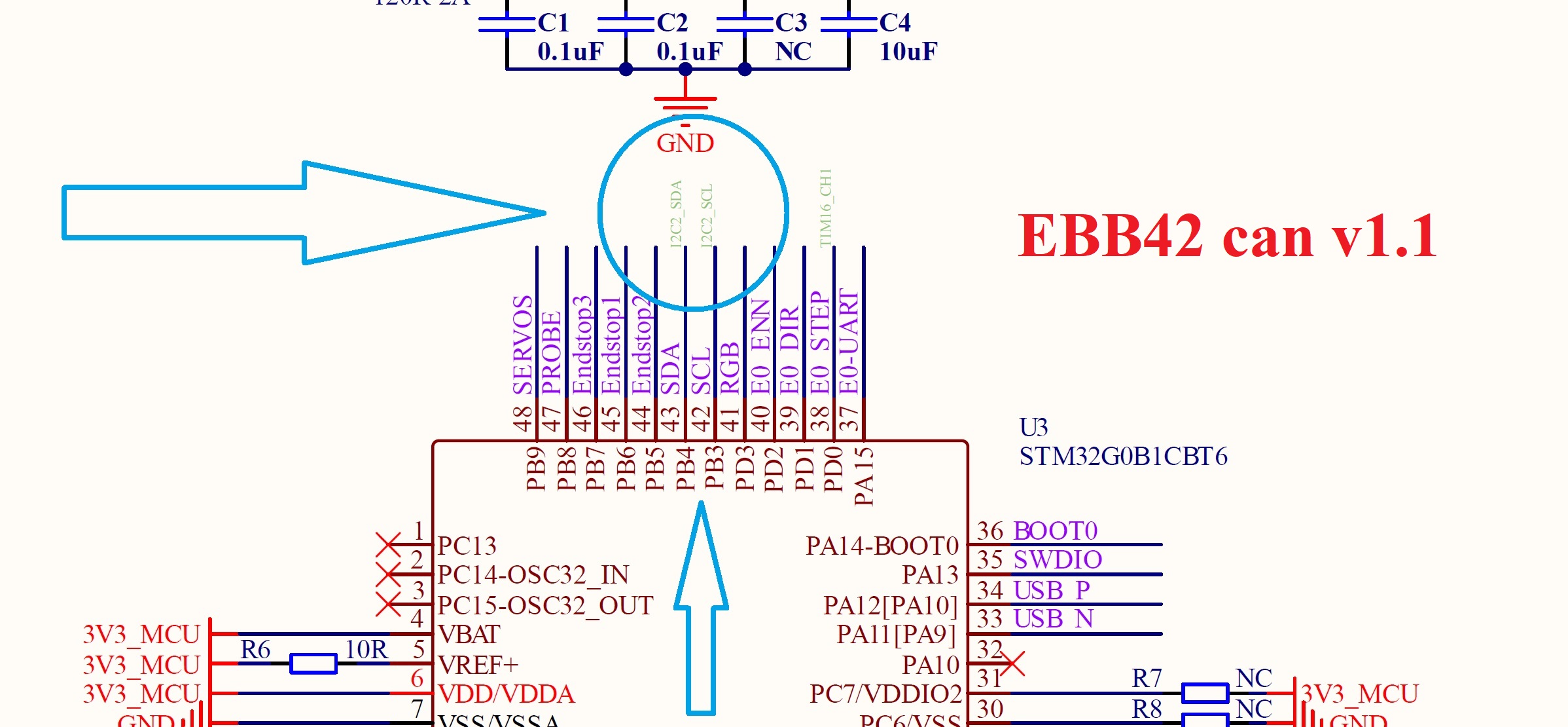
I’m starting to get confused! According to the Klipper BUS_PINS_i2c3_PB3_PB4=PB3,PB4
to the scheme EBB42 can V1.1 or EBB SB2240 — i2c2_PB3_PB4 ???
problem error
Unable to obtain ‘i2c_read_response’ response
log here!
klip.txt (146.5 KB)
!!!my config!!!
[probe_eddy_current btt_eddy]
sensor_type: ldc1612
z_offset: 1 # Set to a non-zero value
i2c_mcu: sb2240 # MCU name of the actual board connected to Eddy Coil
i2c_bus: i2c1_PB6_PB7 # I2C bus actually connected to Eddy Coil
x_offset:0 # Set actual offset relative to nozzle
y_offset: 20 # Set actual offset relative to nozzle
data_rate: 500
I checked the connection of the wire and everything is correct!
it turns out that either the i2c bus is wrong.
or need pull-up resistors!
but the question arises: should I install resistors between 5v and SDA/SCL
But on the Manta MP8 v2. board the pull-up resistors are standing at 3.3v

and so I installed pull-up resistors 4.7K to 5v.
the result is the same! reading i2c error
Maybe I have the wrong i2c bus!?!?!?!
Another attempt to make it all work!
!!!my config!!
[probe_eddy_current btt_eddy]
sensor_type: ldc1612
z_offset: 1 # Set to a non-zero value
i2c_mcu: sb2240 # MCU name of the actual board connected to Eddy Coil
# i2c_bus: i2c1_PB6_PB7 # I2C bus actually connected to Eddy Coil
x_offset:0 # Set actual offset relative to nozzle
y_offset: 20 # Set actual offset relative to nozzle
data_rate: 500
i2c_software_scl_pin: sb2240: PB6
i2c_software_sda_pin: sb2240: PB7
# i2c_speed: 100000
!!!New error!!!
MCU ‘sb2240’ shutdown: soft_i2c NACK
Wow, lot’s of stuff when I first woke up.
Let’s start from what I think is the beginning, you wrote:
When I suggested you use PB6/PB7 on P10/P19 of the SB2240, it was because there are pull ups on the pins already.
Again, looking at the EBB SB2240’s schematic you can see the 10k pull ups:
Next, you put in:
First off, I’m confused by your use of the EBB42 schematic - I’m going by the EBB SB2240.
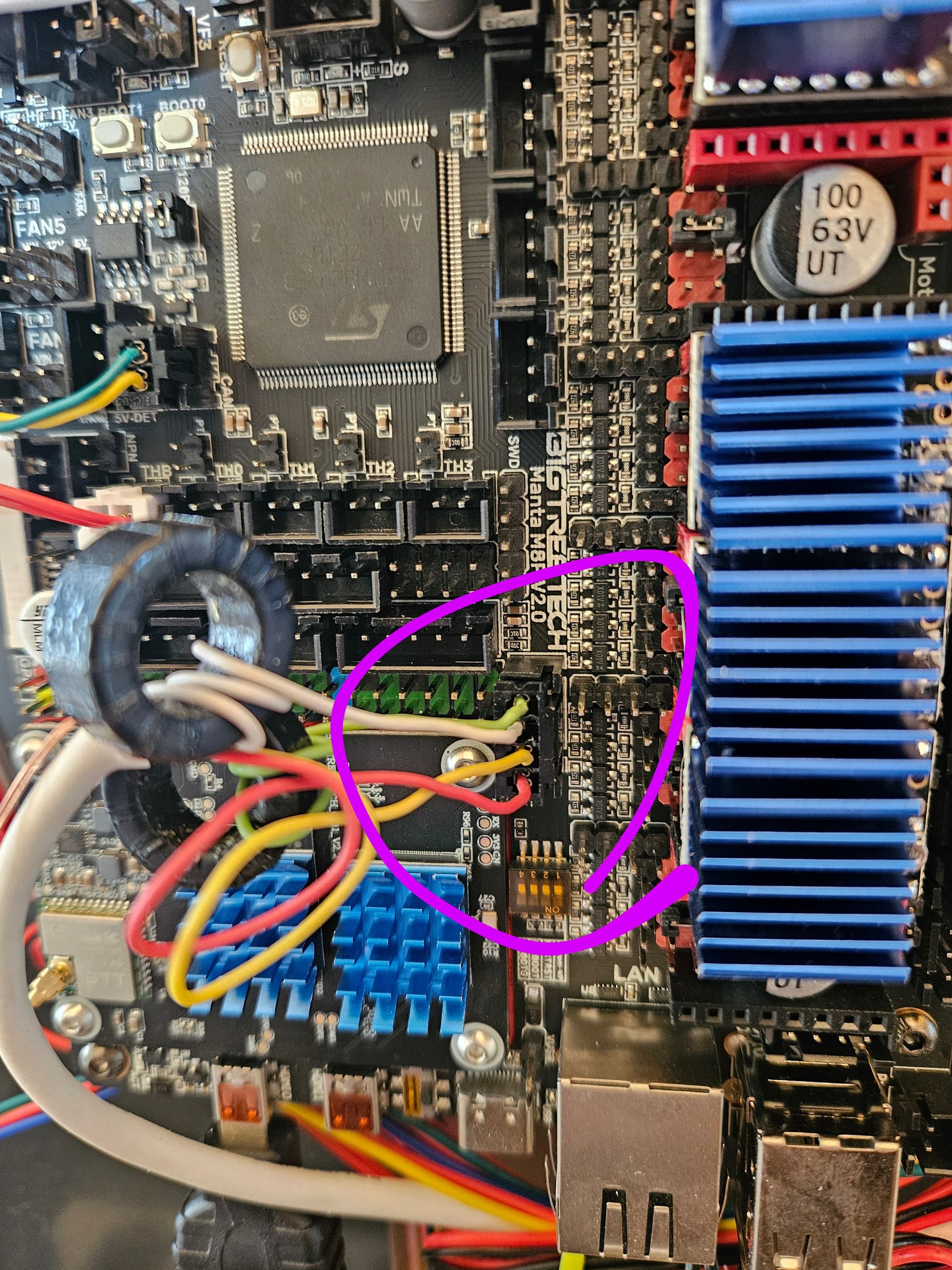
The photograph you’re showing looks like the EBB SB2240:

Regardless, I chose PB6/PB7 as Stop1/Stop2 because:
- There would probably be nothing else connected to them
- They came out to a connector (which I understand you have problem crimping to now - sorry, I don’t have a board in front of me)
- They are the primary I2C bus used by Klipper and the STM32G0B1
I did not choose PB3/PB4 because they are use for other functions on (both the EBB42 and) the EBB SB2240. PB3 is the DIAG0 pin on the TMC driver and can probably be repurposed to being used for the I2C port. PB4 is a no connect on the EBB SB2240 and would be harder to connect to.
Now, you’ve posted:
Followed by:
I’m really confused by where things are now.
Could you:
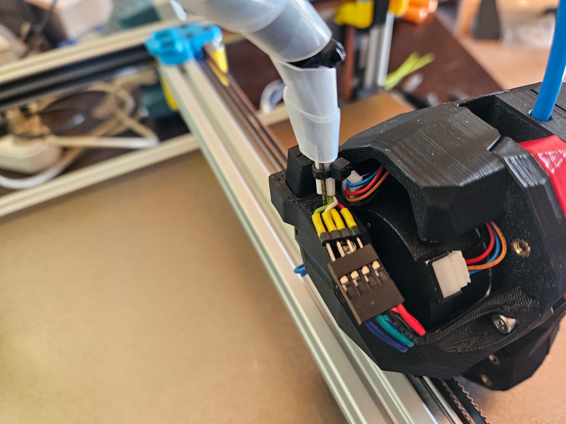
- Give me an accurate state of where things are now and what you’ve done. I think you’re using PB6/PB7, as I suggested but have added additional resistors to the wiring. It might be helpful to provide a drawing/photograph to show exactly what the state of things are.
- When you do a new experiment, show the oscilloscope view of the waveforms. That is really helpful to understanding what is happening as well as getting an idea whether or not there’s a chance that things will work.
- Stop posting abbreviated/edited
klipyy.logfiles. I would really like to see the complete file. If you think it is too large (although you should be able to .zip it and post it here), then do aReseton the Mainsail “Machine” page and then post the new file after you’ve run a new test.
Now, you’re asking about pull ups on 3V3 of 5V. They shoudl be 3V3. The Eddy Coil appears to run on 5V but uses 3V3 logic so the 3V3 pullups built into PB6/PB7 should be fine.
Let’s get back on the same page and work through this.
1 Like
Klipper does not currently support using ldc1612 with i2s_software bus.
i2c_read can be only the Hardware bus here.
Thanks for the information, I’ll come back to i2c Hardware bus
I can’t check with an oscilloscope! Because the signal only goes during the command execution! Because of the error, the signal is immediately interrupted!
So as things stand now! I have a connection now
I connected everything as we agreed) there are no additional resistors!!! I removed them
my head board sb2240!
connection:
PB6 - SCL
PB7 - SDA
!!!my config!!!
probe_eddy_current btt_eddy]
sensor_type: ldc1612
z_offset: 1 # Set to a non-zero value
i2c_mcu: sb2240 # MCU name of the actual board connected to Eddy Coil
i2c_bus: i2c1_PB6_PB7 # I2C bus actually connected to Eddy Coil
x_offset:0 # Set actual offset relative to nozzle
y_offset: 20 # Set actual offset relative to nozzle
data_rate: 500
Now I’ll turn on the printer, I’ll get an error and I’ll post the Klipper log
klippy (8).zip (4.0 MB)
This does not seem to be a valid bus name. Should probably be
i2c_bus: i2c1