Validating TMC2240 operation on Manta M4P - Part 2

Basic Information:

Printer Model: Sapphire Pro
MCU / Printerboard: M4P
Host / SBC: Raspberry Pi CM4
klippy.log (205.6 KB)

This is a follow on to:

With the TMC2240s working with Sensorless homing in a manual stepper setting, I now moved them to a printer (my old Sapphire Pro which is a coreXY that I use for testing).

I changed from [manual_stepper] to [stepper_x/y/z] and I’m now getting

when I start up (see the attached klippy.log) as well as when I try to home/run “G28 X”.

The wiring is the same as what I had when I was just experimenting with the TMC2240s and a simple stepper test and the printer.cfg is the same as what I had with the simple stepper test except I made the change from [manual_stepper] to [stepper_x/y/z]

Can anybody see what I’m doing wrong?

Pins are correct (Manta-M4P/Firmware/Klipper/generic-bigtreetech-manta-m4p.cfg at master · bigtreetech/Manta-M4P · GitHub).
Jumpers, I guess, too.
Do drivers have power?

You could use DUMP_TMC to guess what is wrong with SPI.
IIRC, by default, MISO have pull-up enabled, so you would see 0xff everywhere, if it is not connected.
If there is a bit mess, there is an issue with signaling.

If that’s the case, you could try to decrease the spi_speed to 2000000, for example.

Hope that helps.

Thanx for the suggestion.

Here’s what I got on the console:

10:01 AM SG4_IND:    00000000
10:01 AM SG4_RESULT: 00000000
10:01 AM SG4_THRS:   00000000
10:01 AM PWM_AUTO:   00000000
10:01 AM PWM_SCALE:  00000000
10:01 AM PWMCONF:    00000000
10:01 AM DRV_STATUS: 00000000 cs_actual=0(Reset?)
10:01 AM COOLCONF:   00000000
10:01 AM CHOPCONF:   00000000 mres=0(256usteps)
10:01 AM MSCURACT:   00100000 cur_b=16
10:01 AM MSCNT:      00000000
10:01 AM OTW_OV_VTH: 00000100 overvoltage_vth=0x0100(2.491V) overtempprewarning_vth=0x0000(-264.7C)
10:01 AM ADC_TEMP:   00000000 adc_temp=0x0000(-264.7C)
10:01 AM ADC_VSUPPLY_AIN: 00020001 adc_vsupply=0x0001(0.010V) adc_ain=0x0002(0.610mV)
10:01 AM THIGH:      00000000
10:01 AM TCOOLTHRS:  00000000
10:01 AM TPWMTHRS:   00000000
10:01 AM TSTEP:      0001ffff tstep=131071
10:01 AM TPOWERDOWN: 00000000
10:01 AM IHOLD_IRUN: 00000300 irun=3
10:01 AM GLOBALSCALER: 00000001 globalscaler=1
10:01 AM DRV_CONF:   00000000
10:01 AM IOIN:       00000004 encb=1 version=0x0
10:01 AM GSTAT:      00000000
10:01 AM GCONF:      00000000
10:01 AM ========== Queried registers ==========
10:01 AM MSLUTSTART: 00f70000 start_sin90=247
10:01 AM MSLUTSEL:   ffff8056 w0=2 w1=1 w2=1 w3=1 x1=128 x2=255 x3=255
10:01 AM MSLUT7:     00404222 mslut7=4211234
10:01 AM MSLUT6:     49295556 mslut6=1227445590
10:01 AM MSLUT5:     b5bb777d mslut5=3048961917
10:01 AM MSLUT4:     fbffffff mslut4=4227858431
10:01 AM MSLUT3:     10104222 mslut3=269500962
10:01 AM MSLUT2:     24492929 mslut2=608774441
10:01 AM MSLUT1:     4a9554aa mslut1=1251300522
10:01 AM MSLUT0:     aaaab554 mslut0=2863314260
10:01 AM ========== Write-only registers ==========
10:01 AM DUMP_TMC STEPPER=stepper_x

It looks like communication is happening - I’m not sure about the temperature indication.

I wondered if this another case where the stepper isn’t enabled, so I tried: SET_STEPPER_ENABLE STEPPER=stepper_x ENABLE=1

and this caused Klipper to crash:

So I tried decreasing the spi_speed on all the TMC2240 drivers and no joy on trying to enable them.

Here is the console output with spi_speed: 2000000: for DUMP_TMC STEPPER=stepper_x:


10:15 AM SG4_IND:    00000000
10:15 AM SG4_RESULT: 00000000
10:15 AM SG4_THRS:   00000000
10:15 AM PWM_AUTO:   0000000c pwm_ofs_auto=12
10:15 AM PWM_SCALE:  00000000
10:15 AM PWMCONF:    c0000004 pwm_ofs=4 pwm_lim=12
10:15 AM DRV_STATUS: 00000000 cs_actual=0(Reset?)
10:15 AM COOLCONF:   00000000
10:15 AM CHOPCONF:   00000000 mres=0(256usteps)
10:15 AM MSCURACT:   00330000 cur_b=51
10:15 AM MSCNT:      00000000
10:15 AM OTW_OV_VTH: 01800300 overvoltage_vth=0x0300(7.474V) overtempprewarning_vth=0x0180(-214.8C)
10:15 AM ADC_TEMP:   0000000c adc_temp=0x000c(-263.1C)
10:15 AM ADC_VSUPPLY_AIN: 004c0006 adc_vsupply=0x0006(0.058V) adc_ain=0x004c(23.195mV)
10:15 AM THIGH:      00000000
10:15 AM TCOOLTHRS:  00000000
10:15 AM TPWMTHRS:   00000000
10:15 AM TSTEP:      0003ffff tstep=262143
10:15 AM TPOWERDOWN: 00000000
10:15 AM IHOLD_IRUN: 00000700 irun=7
10:15 AM GLOBALSCALER: 00000002 globalscaler=2
10:15 AM DRV_CONF:   00000000
10:15 AM IOIN:       0000000c encb=1 enca=1 version=0x0
10:15 AM GSTAT:      00000004 uv_cp=1(Undervoltage!)
10:15 AM GCONF:      00000000
10:15 AM ========== Queried registers ==========
10:15 AM MSLUTSTART: 00f70000 start_sin90=247
10:15 AM MSLUTSEL:   ffff8056 w0=2 w1=1 w2=1 w3=1 x1=128 x2=255 x3=255
10:15 AM MSLUT7:     00404222 mslut7=4211234
10:15 AM MSLUT6:     49295556 mslut6=1227445590
10:15 AM MSLUT5:     b5bb777d mslut5=3048961917
10:15 AM MSLUT4:     fbffffff mslut4=4227858431
10:15 AM MSLUT3:     10104222 mslut3=269500962
10:15 AM MSLUT2:     24492929 mslut2=608774441
10:15 AM MSLUT1:     4a9554aa mslut1=1251300522
10:15 AM MSLUT0:     aaaab554 mslut0=2863314260
10:15 AM ========== Write-only registers ==========
10:15 AM DUMP_TMC STEPPER=stepper_x

Note that some of the values are different.

Here is the latest klippy.log: klippy_spi-2000000.log (434.3 KB)

Did you notice the error in the klippy.log of:

Sending MCU 'mcu' printer configuration...
Configured MCU 'mcu' (1024 moves)
TMC stepper_x failed to init: Unable to write tmc spi 'stepper_x' register GLOBALSCALER
TMC stepper_y failed to init: Unable to write tmc spi 'stepper_y' register GLOBALSCALER
TMC stepper_z failed to init: Unable to write tmc spi 'stepper_z' register GLOBALSCALER
TMC extruder failed to init: Unable to write tmc spi 'extruder' register GLOBALSCALER
Starting heater checks for heater_bed
Starting heater checks for extruder
Write g-code response
Traceback (most recent call last):
  File "/home/biqu/klipper/klippy/gcode.py", line 471, in _respond_raw
    os.write(self.fd, (msg+"\n").encode())
    ~~~~~~~~^^^^^^^^^^^^^^^^^^^^^^^^^^^^^^
BlockingIOError: [Errno 11] Resource temporarily unavailable

It looks like something else is happening here.

Alas, it is still looks like random noise; there is nothing I can help with. SPI doesn’t work, and values are off.
I guess, if you try to read several times, there would be different bits.

This is how it should look after the power cycle on TMC2240 (ignore the write-only regs, they are not readable).
You can simply track the temperature/supply voltage output (I do use 25v+, because I can).

$ DUMP_TMC STEPPER=stepper_z
// ========== Write-only registers ==========
// MSLUT0:     aaaab554 mslut0=2863314260
// MSLUT1:     4a9554aa mslut1=1251300522
// MSLUT2:     24492929 mslut2=608774441
// MSLUT3:     10104222 mslut3=269500962
// MSLUT4:     fbffffff mslut4=4227858431
// MSLUT5:     b5bb777d mslut5=3048961917
// MSLUT6:     49295556 mslut6=1227445590
// MSLUT7:     00404222 mslut7=4211234
// MSLUTSEL:   ffff8056 w0=2 w1=1 w2=1 w3=1 x1=128 x2=255 x3=255
// MSLUTSTART: 00f70000 start_sin90=247
// ========== Queried registers ==========
// GCONF:      0000000c en_pwm_mode=1 multistep_filt=1
// GSTAT:      0000001d reset=1(Reset) uv_cp=1(Undervoltage!) register_reset=1 vm_uvlo=1
// IOIN:       4001303c encb=1 enca=1 drv_enn=1 encn=1 output=1 ext_res_det=1 silicon_rv=1 version=0x40
// DRV_CONF:   00000021 current_range=1 slope_control=2
// GLOBALSCALER: 000000eb globalscaler=235
// IHOLD_IRUN: 04061f1f ihold=31 irun=31 iholddelay=6 irundelay=4
// TPOWERDOWN: 0000000a tpowerdown=10
// TSTEP:      000fffff tstep=1048575
// TPWMTHRS:   0000000a tpwmthrs=10
// TCOOLTHRS:  00000000
// THIGH:      00000000
// ADC_VSUPPLY_AIN: 02e70a47 adc_vsupply=0x0a47(25.605V) adc_ain=0x02e7(226.764mV)
// ADC_TEMP:   000008b6 adc_temp=0x08b6(24.9C)
// OTW_OV_VTH: 0b920f25 overvoltage_vth=0x0f25(37.731V) overtempprewarning_vth=0x0b92(120.0C)
// MSCNT:      000003fc mscnt=1020
// MSCURACT:   00f701fb cur_a=-5 cur_b=247
// CHOPCONF:   23400153 toff=3 hstrt=5 hend=2 tpfd=4 mres=3(32usteps) dedge=1
// COOLCONF:   00000000
// DRV_STATUS: 81004000 stealth=1 cs_actual=0(Reset?) stallguard=1 stst=1
// PWMCONF:    c40c001d pwm_ofs=29 pwm_autoscale=1 pwm_autograd=1 pwm_reg=4 pwm_lim=12
// PWM_SCALE:  00000000
// PWM_AUTO:   0000001d pwm_ofs_auto=29
// SG4_THRS:   00000200 sg4_angle_offset=1
// SG4_RESULT: 00000000
// SG4_IND:    00000000

I think it is a consequence of the shutdown.


Btw, can the ADXL be the problem? That stuff, that it is play bad with other devices on the bus.
(you can move it to any free pins/bus, there is SW SPI available).

You’re the man!

I commented out the ADXL345 and disconnected it from the Manta M4P, corrected a spelling mistake in my SGT variable and things started working. I need to see if this is due to the long cable to the ADXL345 (it’s 1.5 metres) or if it’s the ADXL345 itself.

“X” and “Y” don’t move in the expected directions and the SGT value (and probably the homing current), which is correct for the test apparatus isn’t correct here - so, normal tuning operations here.


Once question back to you though before marking this as “Solved”; when I look at the latest klippy.log (klippy_removed_adxl.log (1.0 MB)), I notice that there was GSTAT error on all the drivers with “reset” & “Undervoltage” for the X & Y steppers:

Stats 158.6: gcodein=0 mcu: mcu_awake=0.002 mcu_task_avg=0.000011 mcu_task_stddev=0.000010 bytes_write=3465 bytes_read=8623 bytes_retransmit=9 bytes_invalid=0 send_seq=257 receive_seq=257 retransmit_seq=2 srtt=0.001 rttvar=0.000 rto=0.025 ready_bytes=0 upcoming_bytes=0 freq=64001763 mcu_temp: temp=37.8 raspberry_pi: temp=47.4 heater_bed: target=0 temp=22.7 pwm=0.000 print_time=3.144 buffer_time=0.000 print_stall=0 extruder: target=0 temp=22.5 pwm=0.000 sysload=0.10 cputime=0.801 memavail=1782528
Run Current: 0.30A Hold Current: 0.30A
Stats 159.6: gcodein=0 mcu: mcu_awake=0.002 mcu_task_avg=0.000011 mcu_task_stddev=0.000010 bytes_write=3521 bytes_read=8812 bytes_retransmit=9 bytes_invalid=0 send_seq=261 receive_seq=261 retransmit_seq=2 srtt=0.001 rttvar=0.000 rto=0.025 ready_bytes=0 upcoming_bytes=16 freq=64001741 mcu_temp: temp=38.1 raspberry_pi: temp=46.9 heater_bed: target=0 temp=22.9 pwm=0.000 print_time=14.080 buffer_time=0.165 print_stall=0 extruder: target=0 temp=22.4 pwm=0.000 sysload=0.10 cputime=0.805 memavail=1783168
Run Current: 0.30A Hold Current: 0.30A
Stats 160.6: gcodein=0 mcu: mcu_awake=0.002 mcu_task_avg=0.000011 mcu_task_stddev=0.000010 bytes_write=3669 bytes_read=9110 bytes_retransmit=9 bytes_invalid=0 send_seq=268 receive_seq=268 retransmit_seq=2 srtt=0.001 rttvar=0.000 rto=0.025 ready_bytes=41 upcoming_bytes=0 freq=64001731 mcu_temp: temp=37.9 raspberry_pi: temp=47.4 heater_bed: target=0 temp=22.9 pwm=0.000 print_time=15.347 buffer_time=0.431 print_stall=0 extruder: target=0 temp=22.4 pwm=0.000 sysload=0.09 cputime=0.811 memavail=1783616
TMC 'stepper_x' reports GSTAT:      0000001d reset=1(Reset) uv_cp=1(Undervoltage!) register_reset=1 vm_uvlo=1
TMC 'stepper_y' reports GSTAT:      0000001d reset=1(Reset) uv_cp=1(Undervoltage!) register_reset=1 vm_uvlo=1
TMC 'stepper_x' reports GSTAT:      00000000
TMC 'stepper_y' reports GSTAT:      00000000
Stats 161.6: gcodein=0 mcu: mcu_awake=0.004 mcu_task_avg=0.000014 mcu_task_stddev=0.000018 bytes_write=5416 bytes_read=10510 bytes_retransmit=9 bytes_invalid=0 send_seq=333 receive_seq=333 retransmit_seq=2 srtt=0.001 rttvar=0.000 rto=0.025 ready_bytes=41 upcoming_bytes=0 freq=64001624 mcu_temp: temp=38.1 raspberry_pi: temp=46.3 heater_bed: target=0 temp=22.9 pwm=0.000 print_time=16.212 buffer_time=0.295 print_stall=0 extruder: target=0 temp=22.4 pwm=0.000 sysload=0.09 cputime=0.824 memavail=1783616
Run Current: 0.58A Hold Current: 0.58A

Any comment on this? I don’t think it’s due to not tuning the SGT/homing current values but I thought I’d ask.

Thanx again for the catch with the ADXL345.

I think it is okay. All my drivers (5160/2240/2209) show that on first enable after power cycle.

TMC 'stepper_z' reports GSTAT:      0000001d reset=1(Reset) uv_cp=1(Undervoltage!) register_reset=1 vm_uvlo=1
TMC 'stepper_z' reports GSTAT:      00000000
TMC 'stepper_z1' reports GSTAT:      00000001 reset=1(Reset)
TMC 'stepper_z2' reports GSTAT:      00000001 reset=1(Reset)
TMC 'stepper_z1' reports GSTAT:      00000000
TMC 'stepper_z2' reports GSTAT:      00000000
TMC 'stepper_x' reports GSTAT:      00000005 reset=1(Reset) uv_cp=1(Undervoltage!)
TMC 'stepper_y' reports GSTAT:      00000005 reset=1(Reset) uv_cp=1(Undervoltage!)
TMC 'stepper_x' reports GSTAT:      00000000
TMC 'stepper_y' reports GSTAT:      00000000
1 Like

Just a follow up.

  • With spi running at 2000000 bps, the ADXL345 disconnected and the associated printer.cfg statements commented out - homing and movement work correctly.

  • With spi running at 2000000 bps, a short ADXL345 cable (25cm - 0.25m) and the ADXL345 printer.cfg statements restored - homing and movement work correctly.

  • With spi running at 2000000 bps, the long ADXL345 cable (220cm - 2.2m) and the ADXL345 printer.cfg statements restored - get the errors reported above.

  • With spi running at the default speed of 5000000 bps (I’m guessing this value based on the ADXL345 speed stated here: Configuration reference - Klipper documentation), a short ADXL345 cable (25cm - 0.25m) and the ADXL345 printer.cfg statements restored - homing and movement work correctly.

I made the 2.2m cable to test out the SPI operation of my custom board and I guess it was a good thing because it caught the issue here. Going forward with this printer, I’ll run the ADXL345 from the CM4’s 40pin GPIO connector.


For the Manta M4P, more experimentation needs to be done in terms of SPI operation for multiple devices on the bus and bus length to understand what the practical STM32#### SPI limitations are.

I would try to save you some time.
gpios are driven at the maximum available power on the MCU.
Ref: klipper/src/stm32/gpioperiph.c at master · Klipper3d/klipper · GitHub

SPI hardware block is goofy, so it can only use power-of-2 dividers.
STM32G0 at 64MHz, with a requested 4MHz, would give you that (if you overclock it to 96MHz, it would give you 3MHz on SPI).
STM32H7 at 520MHz, with a requested 4MHz would give you 520_000_000 / 256 = 2031250
Ref: klipper/src/stm32/spi.c at master · Klipper3d/klipper · GitHub

Then there are hardware-specific quirks:

For example, I’m sure that I can produce 8..10MHz signal on Octopus even with long cables to magnetic encoders. But we had issues with step/dir on Manta M8P v2 (H723).
So, I expect they would be on the SPI at a comparable frequency.

This does not mean it is bad; it is intended to work with the default configuration.
IIRC, TMC2240 does support the 10MHz SPI.

This does not mean it is bad or something (for any random reader who can read this), just implementation-specific details.

Hope that saves you some time.

This wasn’t the way to do it. :slight_smile:

Is SPI clocking in Klipper documented anywhere? I’m asking because the documentation for the ADXL345 says that the default datarate is 5Mbps: Configuration reference - Klipper documentation

I guess if a bit-banging SPI interface was selected, then any arbitrary datarate (up to a given speed) could be specified, but what happens with using the built in SPI port?

Let’s just focus on the Manta PCBs because that’s what I’m working with here.

Now, I’ve just gone through all the schematics and your schematic snippet above for the level shifter implementation isn’t correct for SPI lines on the Manta M4P/M5P/M8P V1 boards (it appears to be the signals on the STEP pins and they’re pretty ugly waveforms). I’ll comment on Manta M8P V2 below.

When I look through the schematics for the selected boards, the SPI SCK and MOSI lines fan out to the steppers and the SD Card socket and the general purpose SPI connector. The lines going to the stepper drivers are redriven through CMOS buffers which raise their logic levels to 5V so there really isn’t anything controversial there.

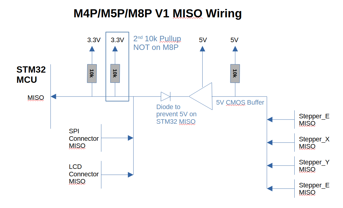
The issue is when I look at the MISO lines on the selected boards. Going through the schematics, they all can be drawn out as:

I haven’t included the decoupling caps on the pull up resistors which may or may not be a factor in the line’s operation and I haven’t put the TVS diode on the 3.3V MISO line. Note that the Manta M8P only has one 10k pullup on the 3.3V MISO line while there are two on the other boards.

Regarding the Manta M8P V2, it has three SPI buses - one for the stepper motors, one for the SD Card slot and one for external devices. This is what I would consider the correct way to implement the SPI connections and should minimize/eliminate the issues I’m seeing here.

Going back to the other boards, MISO is held high unless one of the devices on either the 3.3V or 5V MISO lines are pulled low. There shouldn’t be a problem for the devices on the 3.3V MISO line (the SPI Connector ro the LCD Connector). But, for the stepper MISO lines, there are the pullups along with the capacitance of the line to the SPI Connector. This also includes the capacitance of the diode (which, for the IN5819W used on the Manta boards, is surprisingly high).

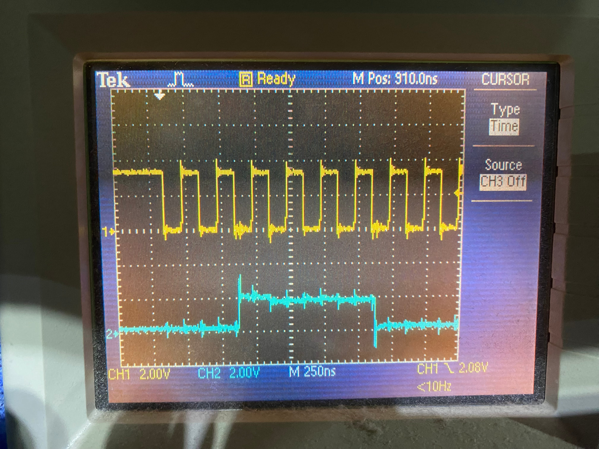
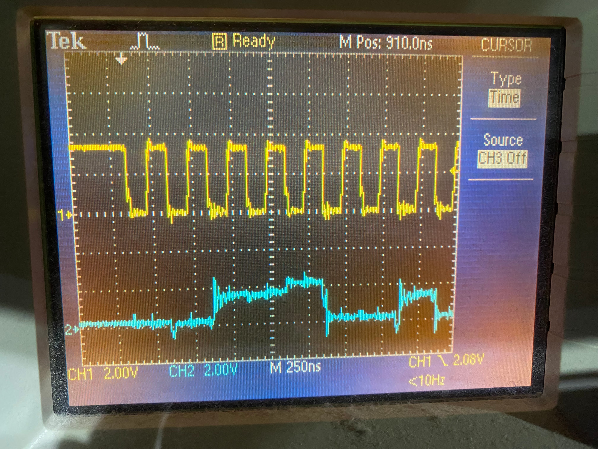
I suspect that if I were to look at the MISO signals provided by the stepper motors at the MCU using an oscilloscope, I would see a pretty distorted signal with the 2.2m long ADXL345 cable in place versus the 25cm cable where things work which would have a more reasonable signal.

So where do I go from here? If I really cared, I’d scope out the lines to see if my hypothesis that the MISO signals on the 3.3V line from the stepper drivers is distorted with the long ADXL345 cable and then cut down the cable to see if that improves the MISO signals and what is the maximum length cable that things work at.

However, I don’t really care. The object of this exercise was to get the TMC2240 stepper motor drivers working with SPI in my printer. I can get the ADXL345 connected to the rPi CM4 GPIO bus so I can have that feature available to me. Now, if this is information that is useful and important to somebody, please let me know and we can talk.

Otherwise, I’m satisfied that my questions have been answered on this issue.

As mentioned real rate is MCU Family/Model specific.
Generally, we try to ensure that the rate is less than or equal to the requested.
Other MCUs would require peeking at the code.

Yes, it supports arbitrary speed up to what the microcontroller can toggle.
It would just require that every device on those pins use the SW SPI.
There is no difference if you use gpio supposed for HW SPI, it is still just a GPIO.

Peeking at the code or using an oscilloscope to determine what it is running at?

I’m guessing that the default has a BR bit (in the SPIx_CR1 register) value of 0, which means the clock runs at one half of the “fpclk” value (which is the APB clock):

Now, the next question is, what is the APB clock value? From what you’ve written above, it’s one half the MCU frequency (so, for a 64MHz MCU, it’s 32MHz).

Now, using the table above for the BR bits, the SPI datarate can be:

  • BR=000 16Mbps
  • BR=001 8Mbps
  • BR=010 4Mbps
  • BR=011 2Mbps
  • BR=100 1Mbps
  • BR=101 500kbps
  • BR=110 250kbps
  • BR=111 125kbps

Going back to the TMC2240, the datasheet says that the maximum SPI datarate is 10Mbps which means that the hardware SPI clock should have BR=001, assuming a 64MHz clock and a 32MHz APB - correct?

Is there an easy way of checking this or do I need to check it on my oscilloscope?

It is still a power of 2.

SYSCLK is equal to the APB for the STM32G0.

I’m not sure it’s worth checking; it would output what is requested or less.
TMC requests 4MHz by default.

The quote fragment doesn’t answer my question. Maybe I wasn’t clear, but what I was asking to confirm how the SPI clock is defined in Klipper for the TMC2240.

I don’t think this is an absolutely valid statement. Looking at the clock tree:

PCLK, which is referred to APB elsewhere, is what drives the SPI Clock (and is passed to the BR[2:0] divider) is derived from SYSCLK but goes through the AHB PRESC and APB PRESC (in the diagram above). Note that SYSCLK is produced by MCO (MCU Clock Output, which is the MCU clock speed, which is normally quoted as the execution speed of the device’s CPU) passes through a divider, which, I guess in this case is a division by 2 (which, I believe is fairly standard for ARM Cortex, at least it’s the same as in other devices I’ve worked with).

If the AHB PRESC and APB PRESC are both 1 then SYSCLK == PCLK or APB.

You passed a link to src/stm32/stm32g0.c which has the high level clock speeds defined but not the actual SYSCLK/APB/actual SPI Clock.

What does this mean?

Without any solid pointers into the code, I think the fastest way of evaluating this would be to pull out the oscilloscope.

It also gives me an opportunity to look at the quality of the MISO line.


Sorry for being so nit picky on this point but I’ve been burned in the past when I’m not 100% sure of how the clocks in ARM Cortex works and what their settings are.

This is how and where the 4MHz default is from.

This is where the TMC2240 imports the TMC2130 SPI definition.

To be specific.

    uint32_t pclk = get_pclock_frequency((uint32_t)spi);
    uint32_t div = 0;
    while ((pclk >> (div + 1)) > rate && div < 7)
        div++;
    uint32_t cr1 = ((mode << SPI_CR1_CPHA_Pos) | (div << SPI_CR1_BR_Pos)
                    | SPI_CR1_SPE | SPI_CR1_MSTR | SPI_CR1_SSM | SPI_CR1_SSI);

PCLK is equal to whatever get_pclock_frequency() returns.

And it returns the value equal to the SYSCLK.

The PCLK is configured in: RCC_CFGR (Reset value: 0x0000 0000)

All bits except the Clock source are zeros.

I would expect it to be equal to SYSCLK.

You can validate the SPI behavior with an oscilloscope.

-Timofey


No problem, generally it is more useful to simply validate what you care, with an oscilloscope or with a logic analyzer.
Because parts of the code can change and may not be tested on every possible MCU.

Thanx for the listing.

I think I found my disconnect. It is here that you highlighted:

The issue here is the (pclk >> (div + 1)) expression.

“pclk” is initially set to 64M which “div” is set to 0 and is used to shift down - BUT adding 1 to it starts the process at 32M, which is the clock rate after the divider passing MCO to SYSCLK in the clock tree diagram I posted above. With adding 1 to the value shifting down the clock speed div is now the value assigned to the BR[2:0] bits and makes sense with what I pulled from the datasheets.


The real issue is that the default Klipper SPI datarate isn’t documented anywhere. It’s also non-trivial to find in the code unless you’re very familiar with it - maybe you have some suggestions on how to make the search easier.

It does not add 1; it shifts the PCLK by DIV + 1.
To account for the fact that BR 0 means divide by 2.
It is not possible to divide by 1 here.

So, all values are shifted by 1 bit.

64000000 >> (0 + 1) > 4000000 -> true -> div++ # 32MHz
64000000 >> (1 + 1) > 4000000 -> true -> div++ # 16MHz
64000000 >> (2 + 1) > 4000000 -> true -> div++ # 8Mhz
64000000 >> (3 + 1) > 4000000 -> false -> div = 3 # 4Mhz

It is confusing there because it probably inherits all defaults from TMC2660: Configuration reference - Klipper documentation.

(But yes, defaults are not always inside the config reference).

Maybe I miss something, but any config section is:
[section_name] in most cases directly translates to the file here: klipper/klippy/extras at master · Klipper3d/klipper · GitHub
For example:
[tmc2240 blah] translates to klipper/klippy/extras/tmc2240.py at master · Klipper3d/klipper · GitHub

So, generally, you could assume it is the name of the file with some code.

There are some exceptions, though (Specific displays and all PTC/NTC thermistors, for example).
For them, it is better to utilize search.

Hope that helps.

Shifting to the right by one is the same as dividing by 2. Shifting to the right a value plus one is the same as dividing by 2^(value + 1) which is what I was trying to explain.

I was noting that the value of “pclk” used in the code was MCO (64MHz - returned by get_pclock_frequency) but SYSCLK/APB is actually 32MHz which means it must be divided by 2 or shifted down by 1 before checking to see if the updated shifting value leads to an acceptable datarate to load into BR[2:0].

A clearer way to implement this code would be:

    uint32_t pclk = get_pclock_frequency((uint32_t)spi) / 2;  //  SYSCLK = MCO / 2
    uint32_t div = 0;
    while ((pclk >> div) > rate && div < 7)
        div++;
    uint32_t cr1 = ((mode << SPI_CR1_CPHA_Pos) | (div << SPI_CR1_BR_Pos)
                    | SPI_CR1_SPE | SPI_CR1_MSTR | SPI_CR1_SSM | SPI_CR1_SSI);

The point was that the (div + 1) didn’t make sense to me until I crawled through the datasheets and understood that the 64MHz MCO had passed through a divider/prescaler (whatever term you want to use) to produce SYSCLK which is the APB clock.


I do know the high level approach for searching the code.

Again, if you’re not intimately familiar with the code, it’s a slog.


I just took a look with an oscilloscope on what I’m calling the “3.3V MISO” and the “5V MISO” on the M4P and the “3.3V MISO” looks pretty bad when being driven high to low by the TMC2240s and I’m experiencing fairly regular Klipper crashes with just the (10x) 'scope probe on the line.

The probe has 12pF capacitance, which is interesting because when I did the capacitance calculation for the 2.2m cable to the ADXL345 it came out to 11.7pF. As I said, the input capacitance of the Diode between the 3.3V MISO and the 5V MISO buffer output is pretty high (about 12pF, according to one datasheet) so the STM32 is probably reading a “High” voltage value for a “Low” bit because the RC decay slope is pretty flat.

I’m looking at buffering the 3.3V MISO to see if I can get solid 'scope pictures.

Incidentally, I had another M4P that I set up by the oscilloscope and its behaviour is identical to the other board.

The conclusion that I’m reaching is that MISO circuitry is pretty marginal.

1 Like

Okay, let’s close this off.

I built a little voltage follower board using an LM324 Op-Amp and powered by the M4P’s 3.3V line and used it to buffer the oscilloscope’s input.

The top line in the following images is the SPI Clock (SCK) and the lower one is what I’m calling the 3.3V MISO. Probing takes place at J58 which is “MCU_DISP_SPI1_EXP3” according to the schematic. Each 'scope picture was taken after executing manual_stepper stepper=stepper_0 enable=1 in the Mainsail Dashboard Console. Vertical deflection on the 'scope is 2V for both SCK and 3.3V MISO.

According to the datasheet, the STM32G0B1 (which is used on the M4P) is designed with a high threshold voltage of 1.9V (Vdd * 0.49 + 0.26V) and is tested at 2.3V (Vdd * 0.7).

The first image is the M4P with no ADXL345 attached to J58. The rise (on bits 2 to 5) on 3.3V MISO is surprising. Note that 3.3V MISO is consistently above the 2.0V line.

The next image is the M4P with an ADXL345 attached to J58 with a 25cm cable. Note that rise over time over bits 2 through 5 is no longer present and the highest value of 3.3V MISO is hovering around 2V and is always less than in the previous image.

Executing accelerometer_query returns valid & consistent values for X/Y/Z.

The final image is the M4P with an ADXL345 attached to J58 with a 2.2m (25cm) cable. Note that the 3.3V MISO signal starts well below 2V in both cases although rises to an acceptable level the longer the signal is high. Klipper crashes consistently when manual_stepper stepper=stepper_0 enable=1 executes

Executing accelerometer_query returns valid & consistent values for X/Y/Z.

The conclusion is to not connect an ADXL345 (or any SPI device) to the J58 connector if stepper drivers with SPI communications is used with any of the stepper drivers.

Thanx to @nefelim4ag for all his help.

1 Like