Array of Poor Corners

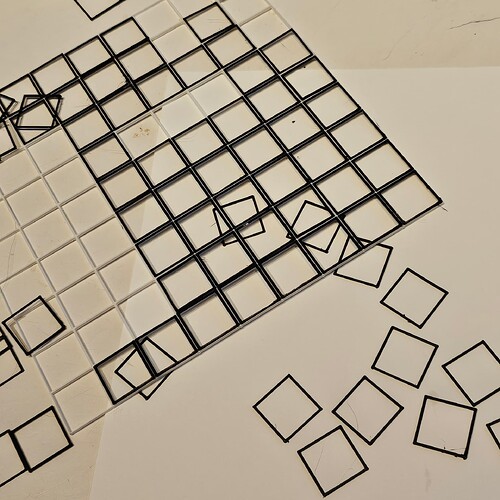
The new method uses the containers, which are in black, and a grid (white) to keep them firmly in place during painting. The white grid is then removed after the painting is completed, while the paint is still wet.

I would like to create super sharp corners, that’s the objective, while I’m here at this point in the development of the painting method. Then, from there, perhaps I will move on to other shapes.

I don’t know how you’d trick the slicer into doing it but now that I see the literal “bigger picture” what would probably make the corners a lot sharper is if it extruded the grid in lines and not tried to draw squares.

You know what I mean? Like extrude the entire column and row width.

But again, I don’t know how to force a slicer to do that. But you could honestly probably write some custom gcode for that since it’s such a simple shape. I don’t know how you’d custom write the extrusion though, you’d have to play around with that.

Edit: Also your project is really neat. I’ve never really been artistically inclined even though I really wish I was sometimes. asthetics escape me, maybe it’s a skill I need to work on like any other, It’s just never “clicked” for me.

For a shape as simple as a square, you might consider rigging up something like a shooting board using sandpaper instead of a plane, and then making several passes on each side of each square to knock the corner bulges down and get a nice sharp corner.

You might also consider using a fine rasp or microplane, or even a something like a “lemon zester” you can usually find in big box stores in the cookware section.

I know this isn’t as satisfying as achieving max dimensional accuracy with your printer, but it might get the job done.

This is true, Or if you really just want to tinker with machines you could always look at getting a K40 laser cutter and make your outline out of acrylic.

But that’s another investment in time and tinkering.

You’ll have the same problem - the laser beam width is not infinitely small, it’s a few fractions of a millimeter in diameter so you can never get anything completely square.

Thank you so much for all this information. I would like to change the resolution by a factor of two (at least), and not infinitely.

This would be from a 0.5 mm radius corner to a 0.25 radius corner.

This is not an arbitrary number. The 0.5 mm radius is maybe too large, and the 0.25 radius is definitely not.

I would just like to increase the precision by a factor of two (at least) or more, to print a very fine corner.

Thus far, it is very close!

I was thinking about the laser cuts from acrylic, earlier (a few weeks ago): The corners do not need to be infinitely sharp. They just need to be twice as good!

If that’s not asking too much!

Thank you so much for your professionalism!

Myke’s comment made me think about something. You’d have the same effect with machining too since endmills are circular you’ll always have a radiused corner.

In that situation what you do to get a sharp corner is you use the smallest end mill you have (and can feasibly use) and then you file out the corners to make them sharp.

Or you use EDM but I don’t think any of us have $100,000’s of dollars for that kind of setup (I could be wrong, but why would they be on a Klipper forum with that kind of money? :thinking: :thinking: :thinking:)

Anyways, Have you considered post processing to get the sharpness you want? It’s just as common to file/sand a 3d print as it is file/sand laser cut acrylic/metal, and machined parts.

It’s more legwork for sure but if sharp corners are your goal that’s one of the quickest ways to get to it.

Remember the CD coaster days? I’m in some “margarita glass drying rack” days, making a lot of margarita glass drying racks.

It’s one step up but I’m almost at my wits end.

I have not been able to improve the 0.5 mm radius corner.

I have adjusted the pressure advance and corner velocities across a large range, and have yet to make any improvements.

I have also been unable to make improvements in the tuning tower.

I followed this up by grepping the klipper-master directory for terms like “nozzle,” “corner,” “radius,” “minimum,” and yeah, “‘0\.5\ mm’” :joy_cat:

I have made at least one hundred Margarita Glass Drying Racks prior, now I may be selling these on Etsy soon because they continue to multiply.

That aside, does anyone know if I could make any improvements on the corner radius using Klipper. I know that I do not know what I’m doing, entirely.

But I had run the aforementioned tests, with the aforementioned results.

I do not believe that I need to use a laser beam to make cuts into some material to exceed the 0.5 mm corner radius, right? Klipper can do this. Right??

Besides, there are other surfaces that I am working with that can not be cut, but on the contrary can be easily constructed using a 3D printer (this is not a problem, but an advantage) … provided I can improve this radius.

[The rails are 0.25 mm wide, and the corner radius is consistently 0.5 mm. So maybe the corner radius is determined by a factor of two, somewhere. Things just got weird. Maybe I just need to make more changes to the corner velocity and pressure advance, IDK.]

I just need to make this “tiny” improvement (a factor of two). Pun intended.

I will be attempting to use 0,1 mm nozzle next, if required. But I would like to read if anyone else has any ideas.

Thank you so much for your replies!

If anyone can, please let me know if there is any weird corner/factor defaults in Klipper, basically.

I didn’t find anything in the impossible to find klipper-master files yet. They are amazing files!
There is nothing in Klipper that sets any kind of corner radius. Klipper reads coordinates from the g-code file (as produced by common slicers) and moves the toolhead to those coordinates as best as it can.

Given the small scales you are working with, I’d guess that you are hitting the limits of the molten plastic. That is, it’s fundamentally difficult to deposit molten plastic through a nozzle such that it remains in a perfect 90 degree shape. Most people that require prints with surface details of that scale will utilize resin 3d printers.

It might be possible to improve the precision of your prints to the point that it meets your requirements while still using an FDM 3d printer. I don’t know of a hard “upper limit” on precision. To get to the next level, though, I’d guess that you’ll need to become an expert on the G-Code format, as I suspect using a typical cad program and typical slicer wont work. That is, I suspect you’ll need exquisite control of the actual coordinates sent to Klipper in order to get that type of fine control.

In particular, if you want a sharp corner, start by making sure the g-code contains a 90 degree angle at each corner (with no fillets of any kind). Once you’ve confirmed the gcode is requesting 90 degree corners, you can measure the deviation, and try to remove that deviation (eg, via pressure advance, velocity settings, or altering the corner coordinates in the g-code).

-Kevin

Sorry, I meant to include this image of the gcode file, which someone “read into AutoCad” that I presume is accurate.

SqCorner.thumb.png.3372c282a57d78e818da7f5e4c6ef8b9

Thanks, koconnor. I read about the resin printing, but I think the design will not survive all the post-processing. The squares are very delicate, and there are 81 of them, in this case.

I’ve also read, over and over again, that the minimum achievable radius on FDM would be comparable to the nozzle radius.

Thus far, I am only able to get 5 times the nozzle radius. :neutral_face:

Have you used a needle gauge to check if your nozzle orifice is actually the diameter you think it is?

Another idea. When I design parts that I want to fit together with tight tolerances, I try as much as possible to avoid any corners of 90 degrees or less. Perhaps you could tweak the model to fillet or chamfer the corners very slightly so that you don’t need perfect 90-degree angles.

1 Like

There is the software GitHub - FullControlXYZ/fullcontrol: Python version of FullControl for toolpath design (and more) - the readme below is best source of information that is reasonably “easy” to use (at least for simple geometries like here) but allows direct control of the gcode without any slicer’s black-box magic.

With it, you could even experiment with things like

  1. Print a line for 20 mm
  2. Stop extruding
  3. Move back 0.001mm
  4. Continue in the 90° direction
1 Like

Hi theofile, thank you for your reply. Good point!

I checked the needles with my calipers, and the 0.15 mm needle went through, and the 0.25 mm needle did not, at all. My calipers were less than 0.05 mm maximum error.

My recollection is I did create fillets of 0.25 mm radius on the outside corners. This radius is the same width as the rails (so as to make a 90-degree corner), and the 0.25 mm radius of the corners are larger than the nozzle diameter. I planned this 0.25 mm dimension based on the width of the extrusion. Maybe there is more I can do in this regard, in terms of extrusion parameters. I almost completely forgot all the parameters and dimensions that I was using.

But something may be “magic” in Klipper, I suspect. The so-called “black=box” is a very apt description (from my perspective)! It’s not like I’m going to open a debugger. It feels like I’m in a storm at sea. :joy_cat:

Maybe it is my machine, but the corners are all so perfect looking — merely a bit large. The machine (Ende-5 S1) has a resolution of 0.1 mm, I perhaps read.

And because the fullcontrol github is very interesting (see proceeding comment), with GB of documentation (it seems), I may try it:

GitHub - FullControlXYZ/fullcontrol: Python version of FullControl for toolpath design (and more) - the readme below is best source of information

Although it’s definitely another learning curve to hike up, argh!

Any other ideas (my legs are tired)? :joy_cat:

Thank you for this!

You could do what I sometimes do, and just give up, lol.
That’s not really true though, cause even when I get frustrated and say screw it (usually in more colorful terms) I usually always end up coming back at some point.

So best I can do is leave you with the old adage, “Nothing difficult is ever easy”

1 Like

I was out of town for a couple weeks with my employer and some staff. We were on a work retreat and it took me several days to recover and catch back up with my day job.

During which, I have since spoken with a friend who recommends just trying these 0.5 mm corners in order to get some paintings completed, and maybe try to work out the details with a paint brush, if needed.

The point of all this was to avoid touching up corners with a brush on 81 squares, because that’s 324 corners! Imagine a larger painting.

Thank you, FuzzyGiggler for your valuable advice, sometimes taking a rest and working with what you have is the best solution. I’ll run some paintings and come back to this problem in a month, if needed.

Learning G-code, and/or running some calculations for Ultimaker extrusion and travel velocities and their derivatives (acceleration and jerk) is some extra work that will require significant time.

Meanwhile, if anyone comes up with a better corner from Klipper settings than 0.5 mm, PLMK !!!

Thank you for all your responses here, everyone!

1 Like

I was out of town for a couple of weeks for my day job. I’m just going with the bird in hand and moving on, it took me a few prints to get back up to speed but things are now snapping into place.

Thank you so much everyone for your advice. 3D printing is non-stop because of you and the 3D printing community.

The photo below is the ‘grid inside grid’ prints that I will next attempt to transfer onto a prepared canvas, and continue with the encaustic and oil color painting technique.

[There is a small break visible on the lower right, but it doesn’t do anything. It just snapped into place like everything else.]

If this works, I will post a video here. If this doesn’t work, I will definitely keep you informed. :joy_cat:

This topic was automatically closed 60 days after the last reply. New replies are no longer allowed.