New to board, just have a question, can the M669 command be used in Klipper? I have designed an IDEX printer that uses essentially a dual Mark Forge style kinematics. This command in RepRapFirmware is as follows:
I am about to publish a paper on this machine and I’d like to determine if Klipper can run it as RepRapFirmware can. I appreciate any input on this. Thanks Gilly
Thank you for this info. I’ll look into the IDEX improvements. I can find little description of the different kinematic drives in Klipper as far as how to implement them. I have looked a bit but I seen to circle back to the same information.
My IDEX printer needs X, U, and Z to have Cartesian type of drive but the Y when moved requires both X and U to react (much like CoreXY). The RRF command looks like this:
M669 X1:0:0:0 Y-1:1:0:1 Z0:0:1:0 U0:0:0:1
Essentially a matrix relating motor movement to linear action. If this style of movement is or could be implemented in Klipper I would add it as a firmware that can drive my machine when I publish it. Any updates on this is appreciated. I’d love to include this community.
I’m afraid what you are looking for isn’t available in Klipper today. M669 command isn’t supported, so you cannot configure a generic ‘cartesian-like’ kinematics, there’s only predefined list of kinematics that are supported (cartesian, corexy/z, hybrid-corexy/z are the relevant kinematics for your case, but these aren’t what you need). But that isn’t the biggest issue. The biggest one is that Klipper natively only supports 4 axes: XYZE. So, while you could have defined your own kinematics class, I suppose your case cannot be supported by Klipper easily today, since Y axis requires native support of U axis (essentially, 4th dimensional axis) to compute its movements.
You can still implement your own kinematics class for your printer and get it to work (especially, once/if my PR is integrated), but it will require some hacking and fiddling around to get it to work. For example, depending on the modes of X and U carriages you get the following movement rules for Y if you trim it to 3 (well, 2) dimensions:
X - primary, U - inactive, Y: -1:1
X - inactive, U - primary: Y: 1:1
X - primary, U - copy: Y: 0:1
X - primary, U - mirror: Y: -2:1
So, all these cases you could cover with corexy_stepper_alloc and dual_carriage_alloc and appropriately configuring x_scale. So, you’d only need to implement some Python code for the kinematics. That said, I’m not sure if you or someone else would be interested in implementing this. But in case there’s some interest in that, you can know that it is doable, in principle, even if requiring certain nontrivial amount of work.
Separately, I am curious about the physical implementation of this kind of kinematics in your printer. At least this isn’t something that most IDEX projects end up implementing.
Thank you for taking the time to consider my question. It’s a shame that Klipper is limited to defined kinematic configurations. Marlin presented me with the same issue. It could be implemented if I trusted my Python programing skills (non-existent). Maybe I can generate enough interest to get someone with skills,…
My IDEX design I call CoreIDX as it started life as a CoreXY. Very minimal changes to the hardware design. Pretty much just added a second carriage/hotend (U) and separated the existing belts, attaching one belt to each carriage. The belt change means a Y drive must be added to move the gantry forward and back. This approach retains most all the advantages of the CoreXY design of low mass and belt tension maintained gantry alignment. I built this on a HEVO frame but the concept could be applied to just about any CoreXY machine, with the caveat of the kinematic requirements. If I still have your interest I will be releasing my printer on Thingiverse soon and more can be found with a Goggle search on CoreIDX.
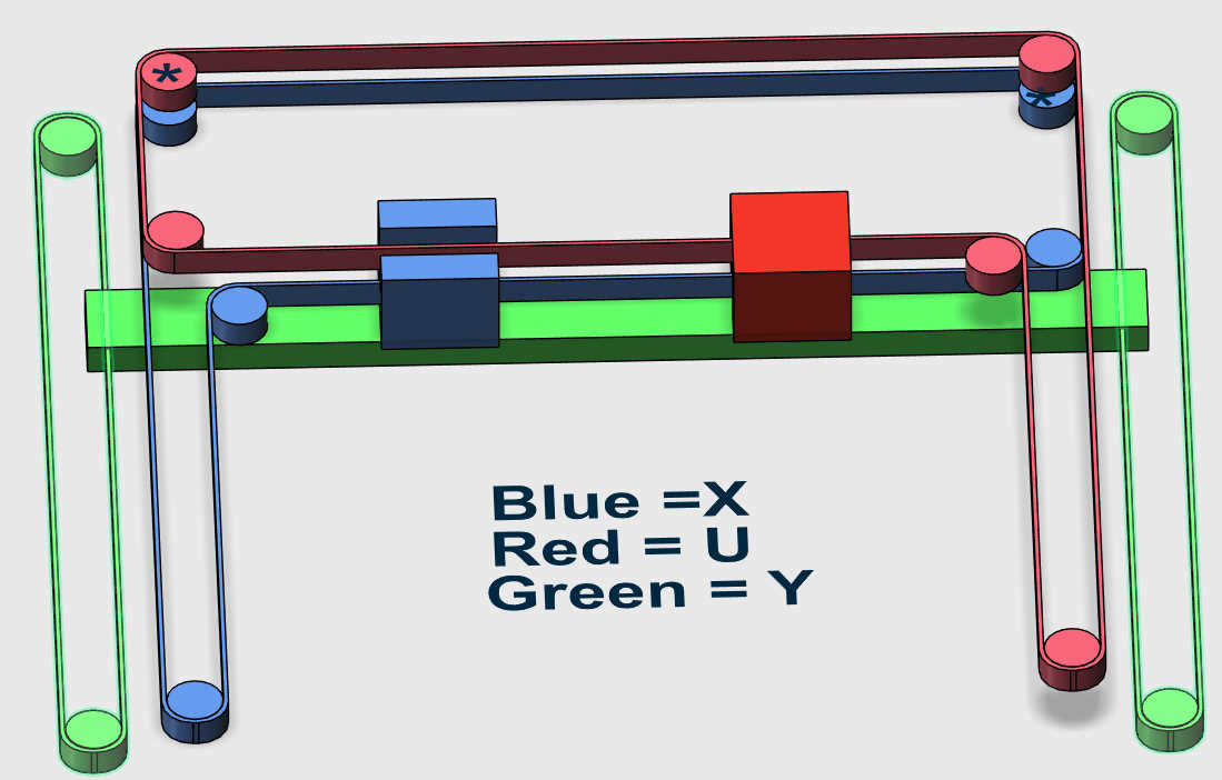
I generally thought about this option, where one could take CoreXY kinematics, and keep one belt attached to the main carriage, and attach the second belt to the secondary carriage. Then one would have to make sure Y axis moves somehow. This is similar to what you describe, but I thought about just taking two stepper motors and connect them to Y axis (or one stepper motor, and connect it via synchronizing shaft on both sides to Y rail):
(consider just the Y axis schematics in this picture)
In such a case, you’d get a kinematics with the rules:
X: 1:1:0
Y: 0:1:0
U:-1:1:0
which is equivalent to hybrid-corexy kinematics that is directly supported by Klipper.
It seems that you’ve made something different for your Y axis. I don’t intend to say that you must change the construction for your printer. You could, however, consider this option, or check whether your expected kinematics actually matches your printer. And note that I don’t have such a printer, so I may have made a mistake in my considerations. Otherwise, the only option is to actually implement this hacky suggestion for the kinematics you’ve built.
What you described is exactly what I have been running for the last 2-3 years. The HaqXY kinematics is exactly what I use, although the equation presented is not quite right.
There should be two equations not one:
X1 = delta B1 - delta A
X2 = delta B2 + delta A
If the gantry is moved in the Y direction (delta A) the two carriages will either move together or apart depending on the direction of that Y movement. Therefore they have different equations that define them.
If you look at the Bottom Core IDX image, there are (*) on two pulleys. Those are the two pulleys that have moved off the gantry of the Dual Mark Forge image you provided to the opposite rear corners of the machine frame. This change provides significant gantry alignment stability just like a CoreXY printer.
So that is what hybrid-corexy kinematics is. The name does not imply that it supports the IDEX functions? Are there existing IDEX Klipper machines that use this style? If so, I’d like to reference them as well as determine if it could work on my system. Really appreciate the update.
OK, I may have misunderstood the format of M669 command. If the picture below describes your printer, then it does seem like it is a hybrid_corexy kinematics with [dual_carriage], which is something that is directly supported by Klipper today. You can check out the relevant documentation in Klipper:
I believe you, but I can not get my head around the config samples sent. I’m old and just used to looking at different code I guess. I struggle to see if these would allow for different formulas for X and U but I can’t get much deeper primarily because it is buried in Python code.
Wait a minute, perhaps a lightbulb moment!
Do you put in the IDEX code in config first, then use hybrid-corexy code twice to
set X to Y and U to Y? Would that define an IDEX “dual Mark Forged” kinematics?
If so, can the movement of X and U be defined differently? X where any Y movement is “added” and U where the Y is subtracted?
Do you know of a IDEX printer that is currently using Klipper “Dual Mark Forged” kinematics? I’d love to see how their config is setup. Thanks again, I’m on a learning curve here.
Note I’ve looked at the github and seems you are the right person to have connected with regarding IDEX and kinematics
No, as I said before, Klipper does not allow custom formulae for kinematics. But what I am saying is that hybrid_corexy already implements the formulae you need both for the primary and secondary carriages. Alas, I cannot help you with the exact configuration because I don’t have an IDEX printer, but I suggest you to try asking a question on Klipper Discord server, perhaps you’d get a faster and more meaningful response. I do believe there are some folks running IDEX printers with “Dual Markforged kinematics” on Klipper.
OK, Klipper has this capability. I’m still struggling to understand your rules as I’m approaching this from a different mindset, but it may be the same actions.
Looking at a set of rules you gave earlier
X: 1:1:0
Y: 0:1:0
U:-1:1:0
Do you look at those rules as a matrix of columns and rows? Please explain.
If a matrix, does the rows represent "linear travel or movement of a carriage " and the columns represents the “motors called to provide that movement”?
That makes sense to me for the X line and the Y line but not the U line.
In my way of thinking, I would have represented the U line like this
As I said, I misunderstood the representation for M669 command, therefore I posted earlier the transposed version of the matrix. Basically, with hybrid_corexy kinematics Klipper supports the following:
stepper_x = x - y
stepper_y = y
stepper_z = z
stepper_u = x + y
where x, y, z are cartesian coordinates, and stepper_x/y/z/u - printer steppers. Klipper does not support ‘u’ coordinate natively, but it allows to switch between the carriages, so that inactive carriage remains still and the active carriage gets gcode ‘x’ as its ‘x’ coordinate (so for dual_carriage gcode x gets mapped to u). Hope that helps.
Superb! Exactly what I had hoped for. I will state that Klipper is capable. I have a raspberry pi I could dust off and I may set this up. Again I appreciate your patience with me.