Your absolute error is NOT related to distance traversed but looks to me to be 90% hysteresis.
The extra load of having to pull the caliper along is probably causing half of it.
What type of printer?
Is the fixed end of the caliper anchored to the bed, upright or X axis rail?
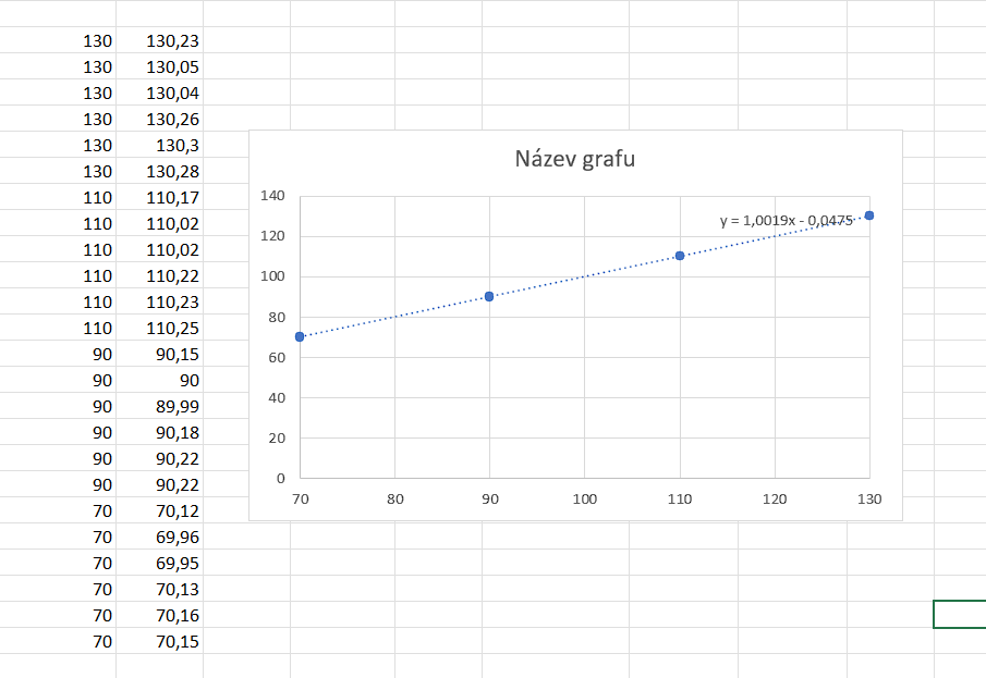
Plot all your data. Target distance on the X axis, actual distance on the Y. Add a trend line and then display the equation. The X coeficent is your linear error (1.005 would be 0.5%).
A couple of other sources of motion errors besides stated above:
Linear distance traveled (and rotation_distance) depends on the belt pitch and not on the pulley pitch. While they should match, in practice the belt can stretch a bit, depending on the quality of the belt and how much [over-]tensioned it was, even in the past, or even how it was manufactured in the first place. This could lead to systematic motion errors.
While a typical stepper accuracy is quoted at ~+/-5% and non-accumulating, which is pretty accurate, this is typically achieved only on full steps (well, with both phases energized equally). In general, the precision of microstepping is not that good. So, you can get random positional errors just based on the start and stop microstep position of the motion, very roughly within ~1/4 of a full step (so, say within ~0.05 mm with 0.2 mm full step).
So in short, 3D printers are not that accurate, getting an accuracy of 0.1mm is fairly good actually. Note that the errors I mentioned are fairly repeatable position-wise, so it means that if you print, say, a vertical wall, its different layers will be stacked on top of each other (assuming the same printing direction) very accurately, far better than 0.1mm accuracy. Just that the position of this wall as a whole can get off by some bit.
DUH - Why didn’t I see that?
Measure 20 teeth on your belt with it installed under tension. That is your rotation distance. No fancy math required.
If you want to be extra accurate measure 100 teeth and divide by 5. If you don’t trust your belt measure 100 tooth spans (overlapping) along your entire belt and average the measurement.
It’s Sunlus S8 (similar to Ender CR10), cartesian type.
Is the fixed end of the caliper anchored to the bed, upright or X axis rail?
It’s fixed to the X rail.
Plot all your data. Target distance on the X axis, actual distance on the Y. Add a trend line and then display the equation. The X coeficent is your linear error (1.005 would be 0.5%).
Yes 0.19%… however your number of data points is not sufficient to support 5 significant figures so the correct interpretation is “no measurable error” and get back to printing.
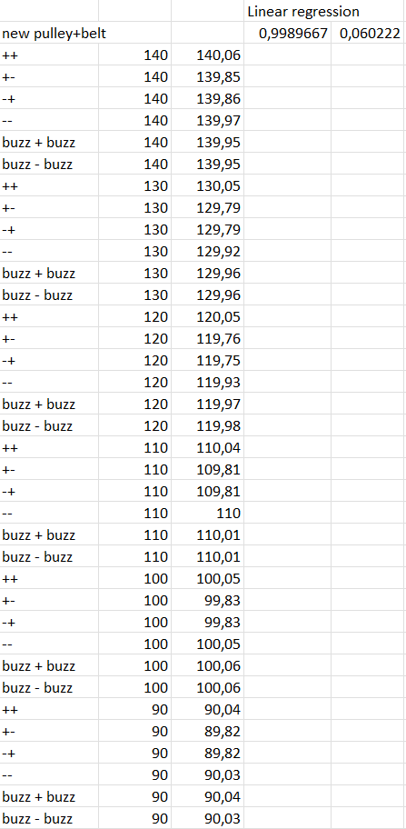
Few interesting things:
Doing ++ ends with correct length and static error around 0,05mm
Doing - - ends, for some reason, with biggest error. I would expect same result as ++.
Overall the error is so small that I will not change anything