Printer Model: Sunlu S8
MCU / Printerboard: Stock with TMC2209
Host / SBC: Rpi Zero 2 W
klippy.log klippy(5).log (309.5 KB)
Hello.
I wanted to check X distance traveled by the printer, so I attached caliper firmly on the X gantry and tool head.
Then I use command FORCE_MOVE stepper=stepper_x VELOCITY=10 DISTANCE=130 to travel 130mm with low speed (to prevent “overshot”). I use force move because the caliper is not long enough to home the axis and I want to do the move in the middle of the X axis.
But I found, that I measure different distance depending on the move direction and depending on the move before/after the 130mm move.
I checked the X axis, everything is tight (motor, pulleys, belt…), belt tension doesn’t have effect to it also.
Only result which is pretty constant and pretty same in both direction is, when I do before and after the move STEPPER_BUZZ.
Here are my measuring (ZC = Zero the caliper).
move +10 → ZC → move +130 = 130,34 mm
move +10 → ZC → move -130 = 130,11 mm
move -10 → ZC → move +130 = 130,12 mm
move -10 → ZC → move -130 = 130,22 mm
buzz → ZC → move +130 → buzz = 130,26 mm
buzz → ZC → move -130 → buzz = 130,25 mm
The 130mm move is always on the same part of the X axis.
Is this normal? It looks like some belt elasticity or something like this.
Thanks for reply.
I tried to increase to 1A (motor should handle it, I lowered it little because they were pretty hot when printing).
The result is the same.
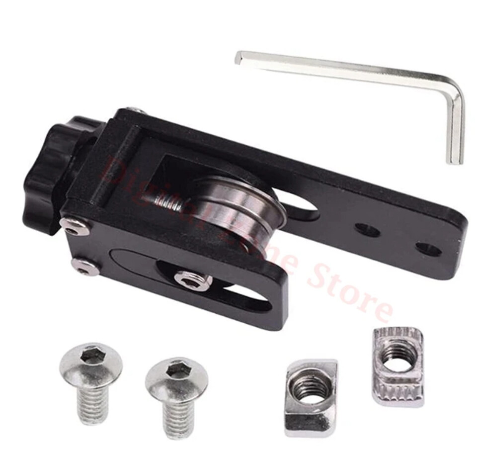
Pulley on motor is tight. Only thing which has little clearance (if it’s the right word) it the pulley on the tightening mechanism. But when I try to move with it by hand, it doesn’t change the measuring, but I will try to do something to tight it up. I use this one:
I tried to replace the tensioner with the original one. It doesn’t have the nice hand mechanism, but it’s rigid. The result is the same.
I use acceleration 1540 (found by input shaper). I tried also with acceleration 10, result is also the same.
Maibe start with a quick caliper test. I had a cheap caliper that acted wierd. Do the same kind of test. Try to beasure something of the same lenght(100-130mm) multiple time. Measure, close te caliper, zero the caliper, measure… 5-6 time, see how it goes.
Maybe you will have a surprise…
But the best test for your x axis is printing. If the print is ok…
The result are still the same and it has the same pattern also with smaller lengths (I tried e.g. 50mm). I have Insize 1108 caliper, which is not the most expensive one, but it’s good caliper (not like cheap aliexpress or Lidl one), so I wouldn’t say that it’s the problem.
Also I did the same test with Y axis and the problem is not almost here (it’s like within 0,01-0,02mm).
I’m trying to get the best from the printer. The output is now pretty good (mainly compared to the state when I bought it as used). I still can see some line imperfections in the prints, that’s why I started to test the mechanics first
The error is still the same, so I don’t think that it’s problem of the measuring itself. It’s more a mechanical problem.
Of course there is some deviation, but it’s like ±0,01-0,02 mm.
I also remounted the caliper maybe more then 4times. I also switched side of the mounting.
I’m thinking about trying to replace the belt.
Do you have any recommendation? I’m in Europe and Amazon is not a good place for me (very expensive shipping). Ideally some reputable seller on Aliexpress…
The fact buzz helps, looks like some part of the system needs to overcome some stiction.
Try mounting the caliper rigidly only on the stationary end and measure carefully by closing the caliper after the move, using the same force each time and repeat the measurement a few times to see the measurement repeats consistently (your closing force + caliper repeatability).
another thing you can try is to change microsteps = 1 so you only get full steps, where torque should be greater. you’ll get crappy resolution and maybe better repeatability.
also as far as absolute values go (and your caliper is to be trusted), where does your rotation_distance come from?:
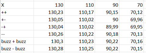
What are your results at 65mm? There are 2 primary error sources; 1) the radius of the belt sprocket 2) mechanical hysteresis.
If you make measurements at say 70, 90, 110, and 130 mm and do a linear regression of the error you’ll find that “m” is the systematic error that can be corrected by changing your rotation distance. The “b” is the mechanical hysteresis which is impossible to fully remove.
Note: the drag of your measuring system will cause MORE hysteresis than actually exists when printing.
Is the shaft if your motor perfectly straight?
Is the hole in your sprocket exactly centered in the OD?
How far off center do the grub screws move the sprocket when tightened?
Is the spring rate of your belt consistent over it’s entire length?
At the end of the day most of theses inaccuracies are lost in the variation in extrusion width from minor errors in filament cross section and imperfections in the contact forces in the extruder to filament interface. Chasing X accuracy to beyond 1% has no net improvement in print output.
3D printers have a very high precision, but accuracy sometimes lacks a bit.
On a back-and-forth movement over a defined distance, all your mentioned points play no role, especially not on a belt-driven system. Each systematic error in one direction is then negated in the opposite direction.
Deviations in the belt or pulley teeth or variances in the motor, e.g., run-out, are periodic errors and might create localized errors but do not create average position errors over a longer distance. This is the reason why such errors cannot be “tuned away”, e.g., by modifying rotation_distance.
The regression will solve for the “best fit” rotation_distance to eliminate as much of the linear error as possible.
This is the hysteresis I spoke of. Impossible to eliminate but can be reduced on most systems.
Once one has eliminated the linear error and understands the hysteresis it is possible to study the periodic errors. On most printers the periodic errors are VERY small.
BUT as I pointed out the error in line width quickly becomes the primary error the makes stressing on the “exactness” of the X and Y moves pointless;
The point I was trying to make is you cannot “calibrate” rotation distance with a single data point. You HAVE to generate a curve or else the hysteresis and cyclic errors will end up in your correction and make accuracy WORSE for moves of other length.
There is a reason any “real” CNC machine has encoders on every axis and used closed loop positioning.
This is correct and since rotation_distance is a single value and not a function, you will at best get an average approximation, which typically is only marginally better (if at all) than just going by the hardware itself.
And on top of this, this is only true once you have excluded all hardware-related, non-linear errors like:
Skewed profiles
Improperly designed or adjusted belt paths
Skewed and non-parallel or non-perpendicular frames