Load Cell Probing Algorithm Testing

I’m in the process of tuning in the Voron test rig for high quality printing. I re-mounted the bowden tube guide the way I had it previously. Now it shakes the toolhead a whole lot more during QGL. The filter work is paying for itself now. That wiggle on the left is, peak to peak, over 35 grams.

This is a bed mesh probe. This is a pattern I’m seeing a lot:

I believe the spike at the pullback move elbow is due to filament sticking to the bed and pulling on the toolhead. Kneedle is doing a good job of picking the right elbow and linear regression is doing the rest of the work to “see through” this.

This is easily the best first layer performance of any DIY printer I have ever built. It’s everything I was hoping for, no going back from this. It certainly seems on-par with the XL. It might be a little bit better because I’m not probing hot (probing at 140C) so I don’t have to deal with all the downsides of their approach.

Accuracy / Repeatability Improvements

So far I have been sticking fairly close to Prusa’s implementation for the tap decomposition. But in October I started messing with various ideas to improve things. I kept seeing seemingly random tap decomposition errors/failures that manifested in a few ways:

  • Crazy plots in the debug tool for data that looked reasonable. This caused the tap to fail.
  • Random probes where the elbow just looked clearly wrong. This would ruin the range of otherwise good set of probes.

Now others are starting to use the test branch and I’m getting access to their probe data. We can see similar effects in their data. I’ve tracked this down to 3 root causes:

Pullback Move Acceleration Data is Unreliable

The samples between when the pullback move starts and when the z axis reaches cruising speed can be chaotic. Sometimes its a flat line, sometimes its a curve, sometimes it looks like movement starts instantly. Making these samples part of the dataset caused the elbow finder to have to solve some kind of Z shaped plot, some of the time.

This had a “tail wagging the dog” effect where the other end of the line would be shifted. The solution here is pretty simple, just completely ignore these samples. I get the timing for the moves from the trapq so I can just drop those samples from the analysis.

This helped but there were still some cases this didn’t fix.

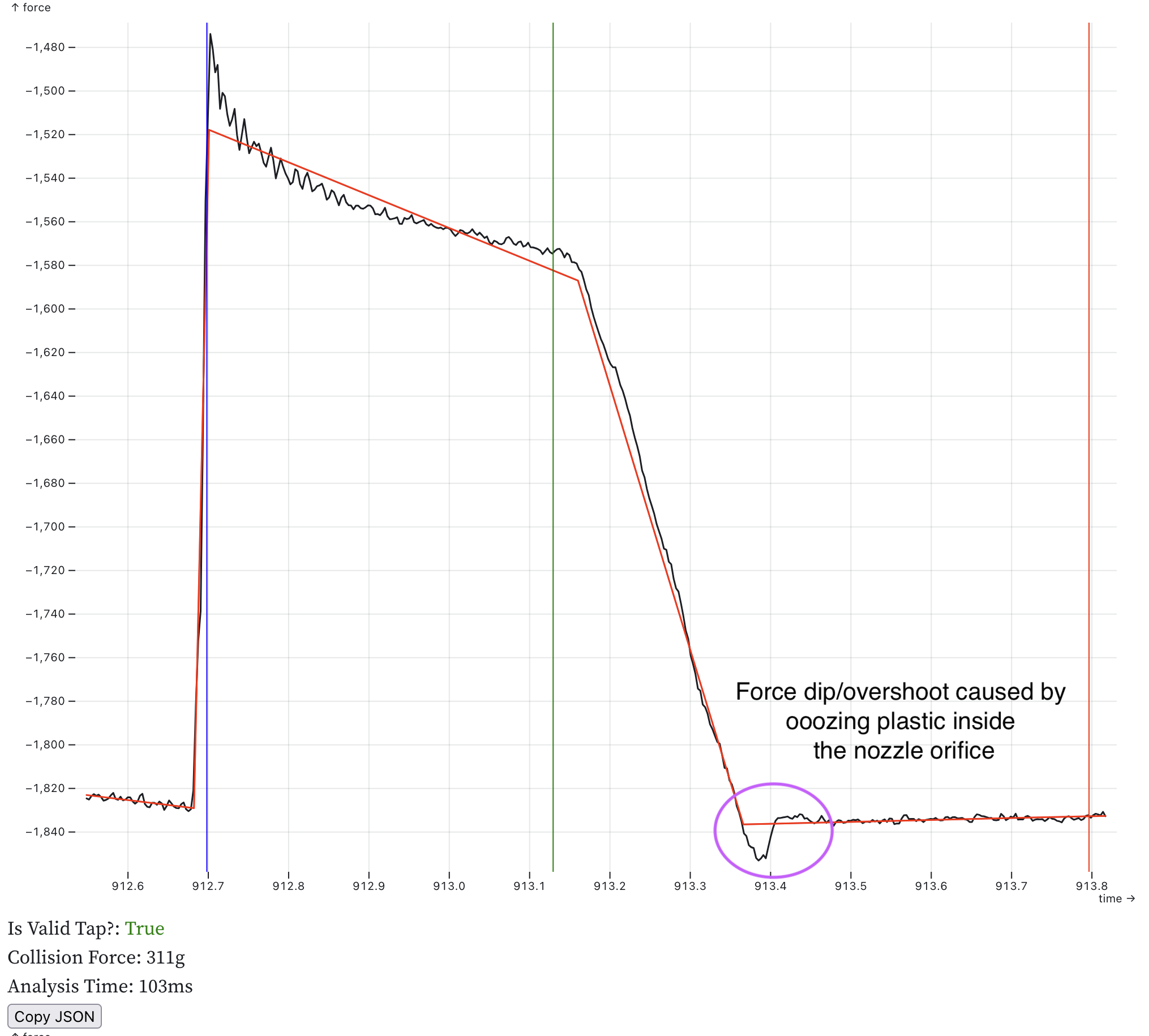
Curves in the Decompression Line

This was way more subtle. The vertical pullback move can sometimes be curved! This is not the underlying assumption of linear regression in this context. Curves really mess with the two_lines_best_fit elbow finder as it tries to optimize a line to pass through that curve. That optimal line is a chord that is tangent and bisects the curve. This is exaggerated but it looks like this:

This puts the ends of the line pretty far away from the actual elbow point causing a large z error (errors in x are error in time which is error in z). The solution I’ve come up with is to break these curves into 2 lines and treat them as two separate line segments. This lends higher importance to points near the elbow causing its position to shift much closer to the real elbow.

The decompression line can be convex, concave or straight. So the solution needs to work equally well for all of those cases. Splitting by time doesn’t work because it unfairly puts puts more information about the curve in one half or the other. I also tried using the elbow finder but this performed poorly. What tested the best is splitting the line vertically on the force axis. This yields 2 line segments that are much closer to reality:

If the line is straight the solution wont change but in curved conditions it improves. I built a notebook to test this on some “difficult” probe data, comparing the old a new approach. Here is a really clear example:

This plot shows the original algorithm in red and the new version in green. The thing to notice there is that the green dot at the last elbow has shifted significantly to the right (every sample here ~= 1 micron in z). There is also a new green dot half way up the pullback line that is the intersection of the two new line segments. And you can see that red line forming the chord through the curve that I sketched earlier.

Here is an example where the line is slightly convex. It still results in a lot or error in the red line:

There are new safety checks with this change. If the tap data is noisy and the tap compression force is small its possible for the split lines to look like noise. So there is a new check for the noise and the curve splitting optimization is disabled if it fails. the split lines need to have points that are more than 2x the noise in amplitude away from the mean. This is an example plot where the safety kicks in and refuses to split the decompression line:

I’m not sure yet how I want to surface this. Its not a failure, but it may mean your setup isn’t optimal. A lower noise sensor, a more sensitive load cell, or just probing faster or with a higher trigger threshold could help.

Kneedle Doesn’t Like Noise

The last batch of issues happened when the Kneedle elbow finder was used to pick an elbow on noisy data. Usually this was the initial collision elbow. That data is noisy because the printer is moving faster when probing downwards. If the noise caused the Kneedle algorithm to pick a bad elbow it could wreck the plot and fail the internal sanity checks.

So I’ve dropped the kneedle algorithm entirely and put some work into optimizing the numpy.linalg.lstsq usage:

  • The nd arrays and transpose matrix get allocated once. Everything is now views, saving a bunch of wasteful memory allocations.
  • I set the data type of the nd array to float32. This aligns much better with the capabilities of the FPU on the Pi for a nice speedup (examples from others).
  • Limit the number of points processed. The code now clips the dataset at 2x the width of the pullback move for any elbow calculation.

Printing with this feels like magic. It just works. I did 3 back-to-back bed sized first layers and they were all defect free. No high spots and no low spots. Just fully fused sheets of plastic.


I still need to do some more work to get these changes pushed out to the testers, but they are coming soon.

6 Likes

Something thing I’ve found in testing is that I cant rely on the results of PROBE_ACCURACY at these small scales.

This is a plot of the absolute Z values of a batch of 50 probes:

There is a very clear upward trend line there. The range is still very small, around 3 microns. But both the range and the standard deviation metrics that PROBE_ACCURACY reports make the underlying assumption that everything about the machine is static. I.e. no thermal expansion, no hysteresis etc. That there is 1 true constant z value for all probes. What I’m seeing tells me this isn’t the case.

So I have an alternate metric I’d like to propose, based on the idea that we don’t actually probe in the same spot 50 times. What we really want to do is probe in 1 spot until we have a good enough idea of the z value there. Really what we want to know is: if I took 1 more probe how different would it be from the last one?

Probes taken close together in time should be consistent. So I take the delta between each pair of probes and average them. I’m calling it average delta. For the above plot this value is about 0.6 microns. This tells you how your probe performs in a way that range and standard deviation are trying to get at but they can be put off by other stuff happening in the printer.

e.g. lets say I do something intentionally bad and kick the heater on and immediately start PROBE_ACCURACY:

// probe accuracy results: maximum -0.083073, minimum -0.113505,
 range 0.030431, average -0.098200, median -0.097071,
 standard deviation 0.009945, average delta: 0.003381

This says that we have a probe with a range of 30 microns and a standard deviation of 10 microns which is usually bad. But average delta is only 3 microns indicating something in the printer was moving around.

When standard deviation and average delta are close it means that the machine was relatively stable:

// probe accuracy results: maximum -0.118461, minimum -0.120276,
 range 0.001815, average -0.119642, median -0.119738,
 standard deviation 0.000512, average delta: 0.000569
6 Likes

The PR with the SOS filter has been posted.

I re-wrote the filter to make it a separate MCU component. Other developers can re-use it in their on-MCU components. As part of the rewrite I changed the implementation from all Q12.19 fixed point to use two different fixed point representations:

The filter coefficients are stored in Q1.30. A sweep of the filter space showed that all of the coefficients that could be generated were less than +/-2. So only 1 integer bit is needed. This helps keep as much of the filter coefficient as possible on the MCU.

The results of the filter and the internal state (zi) are kept in Q16.15. So 16 bits of integer. This choice was mostly to allow other potential users to have some flexibility around how they store their filtered data. Its a balance of integer bits and floating point bits.

I’m converting to grams. 2^16 grams (56Kg!) is way more that I need for a 3D printer probe. There is no physical way to see that force in our flimsy printers. This means overflow is something I don’t believe we need to worry about happening, practically.

But just in case, I have adding overflow checking to the code to make it safer. Previously I was constraining the inputs on the host side so that an overflow was unlikely. But as a general use component that isn’t safe. Now every multiplication is checked for overflow. The filters are also validated before they get sent to the MCU to make sure they fit in the storage datatypes.

Finally you can use the filter without SciPi if you hardcode the filter coefficients. If that’s a tradeoff that you want to make, you can do it. Load cell probes are going to use SciPi to let users easily do filter design from the config file.

All of this brought to you by the SMULL instruction. CPUs are cool :slight_smile:

2 Likes

An open question I’ve had is if filtering the force data before performing the tap analysis would improve anything. My first attempts to do this didn’t result in anything drastically better so I shelved the idea. The best guess I had was that linear regression is the ultimate filter.

Today I went back at it with better statistical tooling. I collected 50 probes and applied 4 different filters to the probe data:

  • None (the control)
  • A notch filter at 60Hz
  • A lowpass butterworth filter at 60hz
  • Both the 60Hz notch and 60Hz lowpass filters

I calculated the standard deviation of each result set and plotted them:

Those lines are all pretty close and so are the SD values. The combined filter seems to be best here, but there is a problem: drift. This graph has a slope, so sd is really measuring how well the filter drops out the slope.

So I tried to remove the slope from the dataset by calculating it and then subtracting it from each datapoint:

Now the Notch filter on its own performs the best. That makes sense:

The high frequency content is random noise. Linear regression slices right through that. But the 60Hz content is power line noise that introduces a local bias at the time where Z=0 is calculated. Filtering that out can change the collision time. Its a small effect but slightly positive.

Edit: Later Gareth here. I have tried a bunch of configurations of filters and different sets of data. I don’t always see an advantage even with the notch filter. 0.00001mm is not a lot of difference. The juice :beverage_box: doesn’t appear to be worth the squeeze :tangerine:.

2 Likes

I’ve started working on the “last” feature which is hot probing. That is, running the nozzle hot enough to glass transition the plastic. Prusa developed this to solve the problem of plastic on the nozzle at the start of the print. It allows them to classify a tap as good or bad in a qualitative way. If the tap is bad they re-measure in a spot that’s adjacent to avoid fouling. This approach works well for bed mesh were the measurement points don’t have to be exact anyway.

The way they achieved this is with Machine Learning, specifically their implementation appears to use Decision Trees. The decision tree is walked and converted into C++ code and patched into the build.

I don’t think their exact code can simply be converted to python and run. It relies on specific features, like time and force, that wont be the same for all users in all configurations ()and certainly isn’t the same between Marlin and klipper.

I’m working on the tooling to develop our own ML based tap classifier models. But to do that it would be nice to have a simpler model that works somewhat ok. A “certified good enough” implementation. If for no other reason than its good to have labeled training data for your model, even if the label is not exact.

So I used my intuition and built one that has 3 simple rules:

  1. The compression force must be least the trigger force
  2. The decompression force should be at least 2/3’s of the measured compression force
  3. The force where the compression starts and where the decompression ends should vary by less than 20% of the measured compression force.

With just that set of rules it spots the majority of low quality taps. If anything its too aggressive. Here its probing at 180C with PETG filament. This is intentionally hotter than Prusa’s setting of 170C, to force it to ooze.

I’m not sure if this is going to work for everyone’s printer. Both the tap classifier and the behavior after a bad tap is configurable in the current codebase.

Here are some examples of things it can detect:

Major plastic fouling of the nozzle:

Build sheet not making firm contact with heater bed:

It detects this but perhaps this should be allowed (too aggressive)

It cant see this case where there is minor plastic adhesion in the nozzle orifice:

1 Like

Nice!
Do we know at which temperature the PEI coating might get damaged, especially with multiple probes to the same spot? The MagnetoX developers recommend a maximum of 165 °C, but they suggested 140 °C when I asked them.

Here is a table of what they do:

Filament Type/Rule Formula Probing Temp
PLA / PETG / ASA / ABS Default 170C
Flex - 210C
PC, PA first_layer_temperature - 25C 250C
Filament Notes contains “HT_MBL10” first_layer_temperature - 10C ???

PEI’s glass transition is 217C, says Google.

Prusa doesn’t have any code to deal with the nozzle elongation due to heating from probing temp to printing temp. So I think they are trying to probe very close to printing temp. But klipper has that with [z_thermal_adjust] so I can compensate for elongation.

They have a material guide and recommend glue stick for all of these high temp filaments as a release agent. This probably provides some protection to the PEI surface.

Up to now I’ve been probing at 140C because basically nothing will ooze at that temp. If you can commit to checking & cleaning the nozzle before the print this works 100%.

But the end goal is a printer that prints with no human interaction. So it has to get hot to clean the nozzle and deal with occasional ooze. We don’t have to do it the way Prusa did, I think the nozzle cleaner stations, like the Bambu machines, is a better idea. But we still want to know when we get low quality taps so we can take corrective action. (also on some machines a nozzle cleaner isn’t practical)

I’m doing QGL and initial homing at 140C. Because they visit the same locations on the bed multiple times, if those locations get fouled, it would fail. For a voron 2.4 I really need a nozzle dock/cap to prevent ooze between prints so QGL doesn’t fail. Every printer is going to need a slightly different solution.

1 Like

I’m a strong believer in load cells. Your measurement from 04.07.2025 are very encouraging, thank you.

Could you give an update about the hardware you used? Sorry, it’s hard to constantly pursue your progress.

This is still coming from my Voron 2.4 with Prusa’s Nextruder mounted to it and their toolhead board that has an HX717 sensor.

I want to build a second test machine but I keep being too busy with software to do that. New hardware is coming. There are projects under development now to give us ways to get these load cells into the more typical toolheads we use today. I’m likely going to wait until I can get my hands on some prototypes to build a new machine.

1 Like

Thanks for the quick reply. One question, what happened with your ADS1220 approaches? Did you dismiss, these boards? If yes, why?

No, I am working on a toolhead board with an ADS1220 on it. I’m still excited about that prospect. I am just prioritizing getting the software merged into klipper over hardware development and letting others lead the way on that.

1 Like