We need a design for a load cell that we can fit into a typical 3D printer toolhead to use as a probe. (This other thread is mainly about the software required for probing.)
There is prior art for this idea:
Duet 3D sells the Smart Effector for delta printers. It uses SMD resistors as strain gauges.
The Prusa XL which looks to be using an aluminum C beam load cell
The BIQU B1 SE PLUS uses a straing gauge on a simple aluminum flexure similar to whats commonly found in bathroom scales.
This thread is to provide a place to discuss and develop this idea further. Ideally we would end up with an open source design that some interested party can manufacture and that open source printer designers (Voron, Rat Rig etc.) can integrate into their tool heads.
Btw: for the Renkforce RF1000 3D printer, there is a 3D model available which includes the load cell construction. It can be downloaded from the German-language forum rf1000.de, here is the direct link (download button only appears after registration+login):
You can also find a FreeCAD version of the model with my personal modifications here (no login required):
I can imagine, the design can be miniaturised a bit by using smaller load cells. In the original it will probably not fit for most printers…
It should also be mentioned that I see two fundamental distinct possibilities to use load cells in the toolhead. Either the load cells can measure any force applied to the hotend, including the force applied by the extruder motor, or they cannot “see” the force from the extruder motor. This has the following consequences (both positive and negative):
With measuring the extruder motor forces one can do interesting things besides probing the print bed. E.g. one can measure the force while printing the first layer, which might increase if the hotend elongates for thermal reasons, to compensate the first layer height (this has been successfully implemented at the RF1000).
If the extruder force is applied to the load cells, those must be stiff enough so that the force won’t press down the hotend too much which would reduce the layer height depending on the current extrusion force.
The RF1000 design can measure the extrusion force and is stiff enough so that it usually does not create problems, but we have seen such effects already if the required extrusion force gets too big (bad hotend, sticky material, high printing speeds - usually a combination of at least 2 of these). As a conclusion I would recommend to make the design either at least as stiff as done at the RF1000 (with 2 load cells rated for 5kg, TAL220B type) or such that the extrusion force is not seen by the load cells. That can be achieved by either putting the motor also onto the load cells for direct drive printers. For Bowden printers the force won’t be applied to the load cells without artificially separating the sleeve from the hotend somehow.
Personally, I don’t see measuring the extrusion force as a killer feature, but others in the RF1000 community will disagree with this statement I am even thinking of changing the construction of my printer such that the motor sits also on the load cells, just to allow easier disassembly/reassembly of the entire toolhead. I am currently not using any feature which makes use of the extrusion force measurement (but I am frequently removing the toolhead, since the printer doubles as a small CNC mill).
One of the nice things we can see from this is what range of force values we need to support. On the high end it seems that 5KG would be the most that an extrusion system could want, with most typically operating under 1KG at sane temps and flow rates. On the low end the Prusa XL was stopping a probe at 50g.
I’m in the camp that primarily wants probing and the other applications are less interesting. The first layer is the hard part of FDM 3D printing. If we can make a significant dent in that issue I’d be very happy. So if I had to pick some things I want I would say:
Very compact so it fits inside the volume of existing toolhead designs between the extruder and the hot end
Sensitive in x, y & z directions @ 50g of load: I want to do x/y probing on my tool changer
Stiff enough that it wont significantly deform under extrusion loads ( maybe 0.05mm @ 1Kg ? )
Safe to operate at 70c in an enclosure
Has some hope of being cheaply mass manufactured
Some less important things:
Thermally stability: we can reset the detection algorithm on probing to deal with this
Linear response to load: you can imagine a sensor that has a non-linear response being just as useful for probing as a linear one. In fact it might be more useful if most of its sensitivity is near 0 force.
Maximum load of 5KG: why are you printing like that in the first place? I’m not building this for your speedboat rig.
I’m very intrigued by the PCB designs with SMD resistors. Given how cheap & easy they would be to manufacture I think we have to prove they wont work before going on to more complex solutions.
50g extrusion force is close nothing. With a E3Dv6 hotend, I typically end up with extrusion forces around 1kg at normal printing speeds and easy materials. If one starts tuning for higher speeds or starts to use other materials (e.g. PETG has a tendency to stick to all-metal heat breaks), extrusion forces of say 2-3 kg are pretty normal. Hence I would say 5kg is a reasonable maximum design load for an average printer, since you need some headroom between a typical scenario and the maximum acceptable situation. My printer has a pair of 5kg load cells, so the maximum acceptable force is even higher (but not twice as high, as the forces are not evenly distributed).
I would recommend considering available off-the-shelf load cells before getting into the business of designing your own. You can buy a variety of differently shaped load cells for not so much money, you just have to think about how to get them where you need them. Maybe for first tests and gaining experiences I would recommend even to live with a potential reduction of the maximum print size (if the load cells are too big and will hit some other components at the edges of the axes). This will help you understand what to expect and what to optimise your custom design for.
If you are not planning on measuring the extrusion forces, things will also be more relaxed.
Just want to chip in my two cents to the mechanical design. If we want to go for off-the-shelf cheap load cells, those are quite bulky. Hence orienting them for direct measurement will not allow sticking to conventional toolhead packageing.
Hence, here’s an idea: how about using a lever to change the direction of the forces registered by the load cell.
If we go for a levered design, we could amplify forces mechanically, which could increase the sensitivity of the measurements. Besides, a lever allows limiting forces on the load cell as it can be designed as natural breaking point. A Lever would also be most sensitive around cero load.
If you think this may be of interest, I could work on a design. I’m currently on business trip and thus could look into this in a couple of weeks. Regarding xyz measurements, this is probably very tricky to achieve. The other design requirements should be doable.
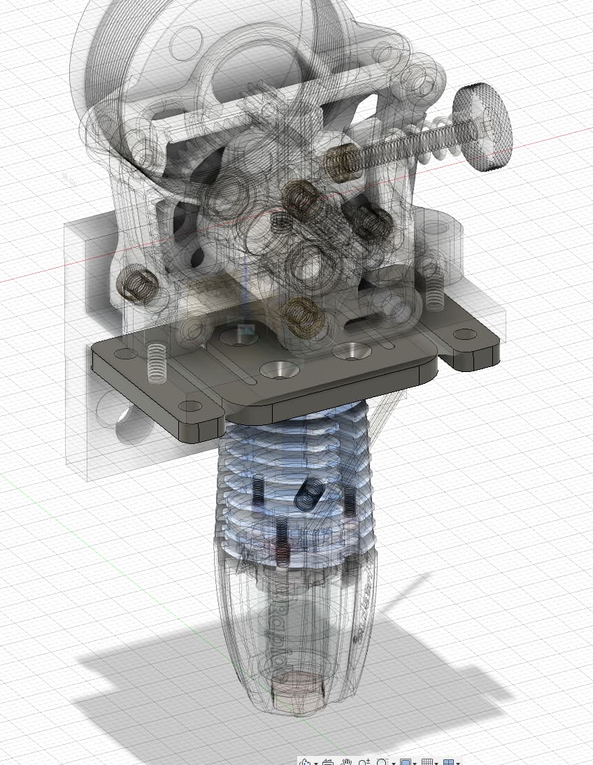
My custom Rapido heat sink is mounted to the underside of the tongue. You could also mount the standard Rapido (or other brand) heat sink in the same fashion.
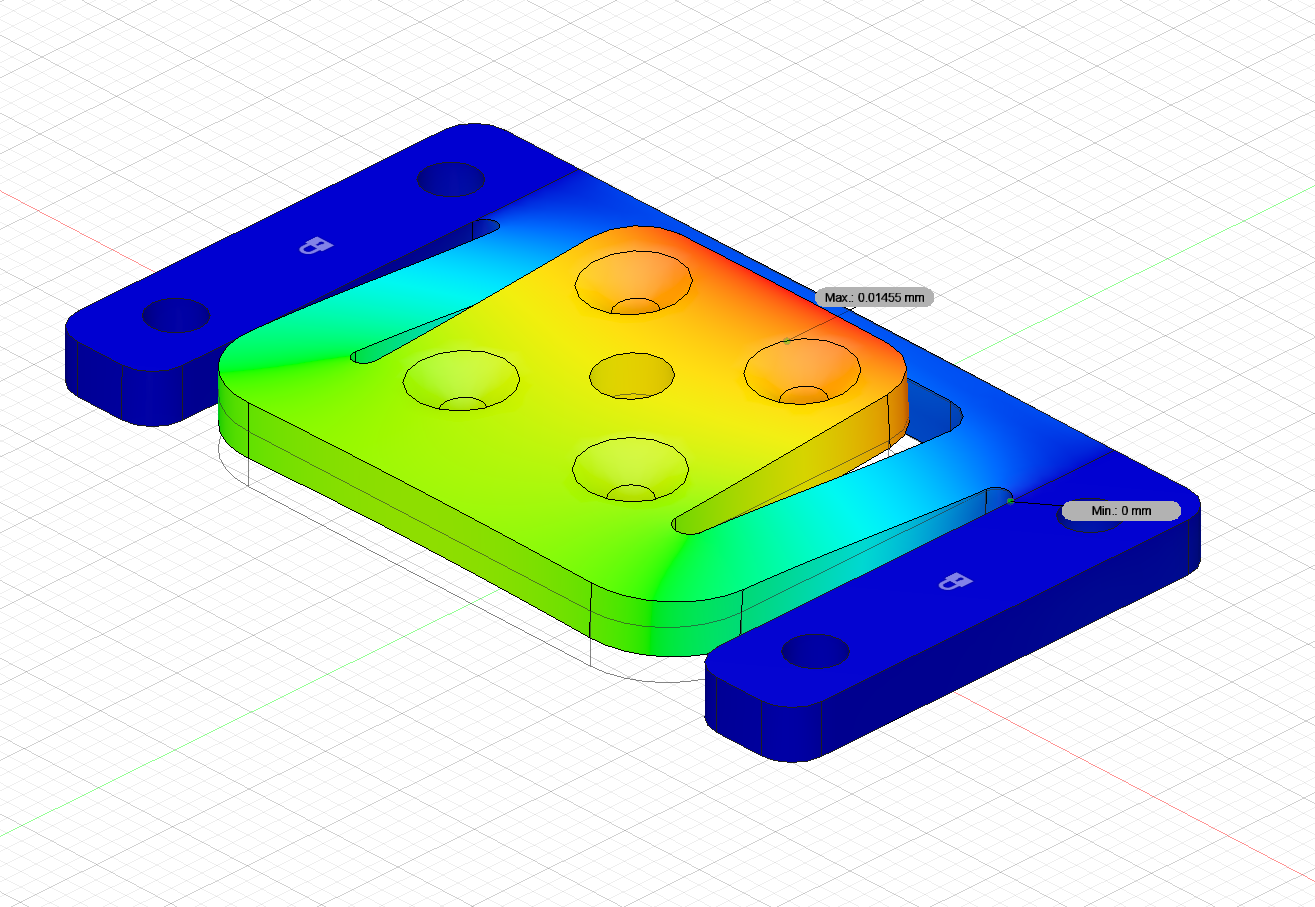
very flat, light and does not take much space between hotend and extruder
could be made by laser
Cons:
forces modify the hotend position and angle (if only one plate). This could potentially influence the zero point of the hotend nozzle dependent on the extruder force in y-position. Could be negliglible dependent on the resolution of the strain gauges
From what I read we aim for:
5kg max detection
possible endstop to not damage the strain gauges
5g min detection force for touch?
temperature compensation, obviously (0-100°C?)
something else ??
The hard part is selecting the strain gauges. There are thousands for different applications.
This might be a bit too low, at least I would strongly recommend to design it such that nothing gets damaged if ~10kg force is applied. Exceeding 5kg can happen even during somewhat normal printing conditions.
Beware this does not translate into the least significant bit being equivalent to 5g, nor does it mean the noise band can be the equivalent of 5g. You need to be significantly better than this. My setup has roughly 1g as the least significant bit basically noise free (noise is well below ADC resolution), which I would consider right at the edge. The original firmware (without linear regression) uses a (non-static!) threshold of around 5g (exactly 5 digits) for the contact detection. With “non-static” I mean: a higher threshold is applied for the first approach to find the rough position, then the tool head will back off until the value is below the 5 digit threshold again. This approach works relatively well, but still has a remaining static offset which should be corrected manually.
I don’t know if we can get a sensor thats capable of measuring 1g and 10kg simultaneously, that seems to be hard as far as I have researched. But the max. detectable force and the max. safe load before breaking are two different parameters. We could design an endtsop that takes the load if its higher than the detectable force.
Well, I have a pair of load cells (type TAL220B, each 5kg max, so 10kg in total) attached to an amplifier with an ADS1100. This is capable of doing that. The design is bulky, ok, but maybe you can find something smaller.
Besides, the electronic design is openly available:
Second page “DMS Verstärker und A/D” (-> strain gauge amplifier and A/D) is the right section to look at. Maybe it helps as a reference (I do not necessarily recommend to rebuild it, as I expect you can do better nowadays - this is 10 years old).
I think this is a good reason to look at designs that have both a support member and a separate flexure. We can support the bulk of that 12Kg with the supporting member and then put the strain gauge on the flexure.
I don‘t know if i understand the concept of that split design completely. I will look into it.
So lets aim for 10kgs (edit: more than 12 ) then. I see potential problems in the displacement of the nozzle if you apply a force of 10kgs to a structure that bends enough to detect it when theres only 1g applied. Thats the difference here, the kitchen scale does not care if the platform moves 0,1mm. So the stiffness and measuring resolution are contradictory requirements, let’s figure out whats best in between.
That might be a good idea, although one should take care in the design that thermal expansion of the parts does not lead (considerable) measured forces on the load cells. To some extend, my printer already suffers from that, because it has two load cells in parallel. If the traverse between the two load cells expands differently than the support structure, there will be forces applied to the load cells which can change the “baseline” of our measurement. If the effect is small enough, it can be compensated by software (we have discussed this quite often), so the advice is to keep it small by design
You are pointing out a true issue. I am observing with my printer that the nozzle is moving slightly downwards when high forces are applied. Even a 10 micrometer change is already 10% of a 0.1mm layer height, which means then 10% over-extrusion in one moment paired with 10% under-extrusion at some point later (when the force is lower). We (the community around my printer) has experimented with compensating this in software my moving the z axis in dependence of the measured force. It is very much preferred of course to keep this effect as small as possible, since not having an error is always better then compensating for it… IMO this speaks totally against these attempts to make home-brew load cells using resistors on a PCB.
Besides: many load cells have a geometry which makes them move as a parallelogram rather then bending. This is the case for these bar-typed load cells with an elongated hole drilled through from the sides (like my TAL220B). This will at least eliminate the tilt and hence keep the nozzle in place in X and Y.
Yes, I agree that pcbs won’t be a good idea.
I actually came to the same conclusion - we need a parallelogram as load cell to not mess up the angle. XY will still be affected, but it will be negliglible.
Maybe we need an software option for z-compensation of the extrusion force in z @garethky ? With additional calibration routine? Could be like measure z-offset without extrusion force and with predefined extrusion force to get the factor between extrusion force and z-offset?
Another Idea: One load cell for the hotend to measure z-offset (mechanical lower limit, hotend can only move up) and one load cell for the extruder to measure the pressure advance:
It’s a parallelogram, the bottom is a solid arm, so it holds most of the load, maybe 80% (10Kg). The top has the flexure cut into it, so it holds less of the load (2Kg). The result is that you have to bend the bottom arm to deform the loadcell. But the entire structure can sustain higher loads than the flexure alone can.