Hi,
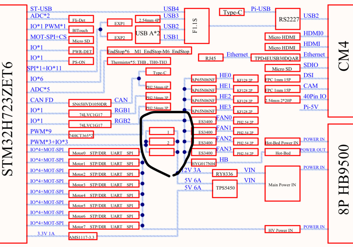
I was wondering if someone could please clarify what part of the Manta M8P V2.0 board these blocks that I’ve circled are? I was wondering if I could run a few servo motors that would collectively draw up to about 4.5 A with this board along with other peripherals such as a Camera and touch screen connected to the USB and micro HDMI ports on the side of the board? I was initially thinking to connect my servos to one of the 5 V ports of an unused end stop but I realised that it actually has a current limit of 3.6 A due to the efuse for these end stops as per the schematics.
When I looked at the schematics I also found that there is a 6A limit for the output that gets dropped down from the TPS5450 converter. Although, it was a bit unclear as to where this 6A output ends up going before feeding into the PWM pins of the STM mcu as you can see in the section I’ve circled below. I was also wondering is the 5V used to power the CM4 the same 5V rail as this one coming from TPS5450?
I also wanted clarification as to how I can figure out how much current draw a camera and touch screen module would have from the usb and hdmi ports if at all and whether this and the Pi need to be added up before figuring out if I can safely connect all the servos? I may end up just using an external 5V DC power supply if the current draw from the board will be too excessive considering the camera, touch screen, a reflectivity sensor and CM4 I have connected.