config-20240920-224512.zip (8.8 KB)
Okay, question for you.
I’ve been scouring the klippy.log and one thing doesn’t make sense.
First off, for the run that starts at Wed Mar 20 23:42:14 2024 (1710978134.4 1522.6) (I’m guessing you haven’t set your date and time properly) the btt_eddy statement is:
[probe_eddy_current btt_eddy]
sensor_type = ldc1612
z_offset = 1
i2c_mcu = sb2240
i2c_bus = i2c1_PB6_PB7
x_offset = 0
y_offset = 20
data_rate = 500
calibrate =
	0.050000:3207699.594,0.100000:3207141.189,0.150000:3206564.339,
	0.200000:3205998.528,0.250000:3205421.329,0.300000:3204883.073,
	0.350000:3204292.184,0.400000:3203773.146,0.450000:3203294.481,
	0.500000:3202757.730,0.550000:3202274.951,0.600000:3201774.550,
	0.650000:3201297.859,0.700000:3200833.363,0.750000:3200338.938,
	0.800000:3199845.502,0.850000:3199407.159,0.900000:3198946.967,
	0.950000:3198530.107,1.000000:3198082.834,1.050000:3197664.912,
	1.100000:3197276.036,1.150000:3196856.075,1.200000:3196451.244,
	1.250000:3196078.298,1.300000:3195679.907,1.350000:3195317.339,
	1.400000:3194942.274,1.450000:3194586.297,1.500000:3194228.212,
	1.550000:3193862.701,1.600000:3193531.575,1.650000:3193212.875,
	1.700000:3192868.353,1.750000:3192565.119,1.800000:3192225.248,
	1.850000:3191914.767,1.900000:3191612.717,1.950000:3191313.087,
	2.000000:3190989.028,2.050000:3190716.184,2.100000:3190420.831,
	2.150000:3190181.490,2.200000:3189895.656,2.250000:3189617.857,
	2.300000:3189364.023,2.350000:3189101.713,2.400000:3188853.082,
	2.450000:3188591.115,2.500000:3188374.243,2.550000:3188117.857,
	2.600000:3187888.238,2.650000:3187649.940,2.700000:3187435.040,
	2.750000:3187194.958,2.800000:3186970.903,2.850000:3186768.375,
	2.900000:3186547.824,2.950000:3186341.320,3.000000:3186143.320,
	3.050000:3185920.156,3.100000:3185734.683,3.150000:3185529.662,
	3.200000:3185330.516,3.250000:3185135.867,3.300000:3184957.732,
	3.350000:3184787.230,3.400000:3184617.410,3.450000:3184430.081,
	3.500000:3184274.324,3.550000:3184080.004,3.600000:3183911.964,
	3.650000:3183775.656,3.700000:3183615.235,3.750000:3183438.456,
	3.800000:3183266.390,3.850000:3183143.953,3.900000:3182988.757,
	3.950000:3182845.322,4.000000:3182721.499,4.050000:3182564.965
reg_drive_current = 15
calibration_temp = 0.000000
and it generates the error:
pins.error: Unknown i2c_bus 'i2c1_PB6_PB7=PB6,PB7'
While the last test (at Wed Mar 20 23:44:40 2024 (1710978280.4 1668.7)) has the `btt_eddy’ statement:
[probe_eddy_current btt_eddy]
sensor_type = ldc1612
z_offset = 1
i2c_mcu = sb2240
i2c_bus = i2c1_PB6_PB7=PB6,PB7
x_offset = 0
y_offset = 20
data_rate = 500
calibrate =
	0.050000:3207699.594,0.100000:3207141.189,0.150000:3206564.339,
	0.200000:3205998.528,0.250000:3205421.329,0.300000:3204883.073,
	0.350000:3204292.184,0.400000:3203773.146,0.450000:3203294.481,
	0.500000:3202757.730,0.550000:3202274.951,0.600000:3201774.550,
	0.650000:3201297.859,0.700000:3200833.363,0.750000:3200338.938,
	0.800000:3199845.502,0.850000:3199407.159,0.900000:3198946.967,
	0.950000:3198530.107,1.000000:3198082.834,1.050000:3197664.912,
	1.100000:3197276.036,1.150000:3196856.075,1.200000:3196451.244,
	1.250000:3196078.298,1.300000:3195679.907,1.350000:3195317.339,
	1.400000:3194942.274,1.450000:3194586.297,1.500000:3194228.212,
	1.550000:3193862.701,1.600000:3193531.575,1.650000:3193212.875,
	1.700000:3192868.353,1.750000:3192565.119,1.800000:3192225.248,
	1.850000:3191914.767,1.900000:3191612.717,1.950000:3191313.087,
	2.000000:3190989.028,2.050000:3190716.184,2.100000:3190420.831,
	2.150000:3190181.490,2.200000:3189895.656,2.250000:3189617.857,
	2.300000:3189364.023,2.350000:3189101.713,2.400000:3188853.082,
	2.450000:3188591.115,2.500000:3188374.243,2.550000:3188117.857,
	2.600000:3187888.238,2.650000:3187649.940,2.700000:3187435.040,
	2.750000:3187194.958,2.800000:3186970.903,2.850000:3186768.375,
	2.900000:3186547.824,2.950000:3186341.320,3.000000:3186143.320,
	3.050000:3185920.156,3.100000:3185734.683,3.150000:3185529.662,
	3.200000:3185330.516,3.250000:3185135.867,3.300000:3184957.732,
	3.350000:3184787.230,3.400000:3184617.410,3.450000:3184430.081,
	3.500000:3184274.324,3.550000:3184080.004,3.600000:3183911.964,
	3.650000:3183775.656,3.700000:3183615.235,3.750000:3183438.456,
	3.800000:3183266.390,3.850000:3183143.953,3.900000:3182988.757,
	3.950000:3182845.322,4.000000:3182721.499,4.050000:3182564.965
reg_drive_current = 15
calibration_temp = 0.000000
Note that the i2c_bus statement is different in the two cases and in the second case, there is a completely different error.
The printer.cfg you shared with me has the same btt_eddy statement as the second to last case.
Are you changing the printer.cfg with each test?
If so, that’s fine, but I need to know that AND I would appreciate you checking the operation with your oscilloscope as well.
As I said above, the goal right now is to see if we can get the lines wiggling and to do that, I need all relevant information including any software changes.
I deleted the calibration information!!! watch log
klippy (10).log (179.2 KB)

I was selecting different bus name ports)
that’s why there are different errors

I’m trying to go through the python and it seems like your failing on the retry loops.
I’ve reached out to @nefelim4ag to comment - he seems very familiar with the software.
If you’re really itching to make some progress hhe only thing I can suggest, until he replies, is to change the I2C port to i2c3_PB3_PB4 (you asked about that above) and see if the lines change state.
However, I’m sure @nefelim4ag will get back to us and comment in a few hours - Either there’s something very basic that we’re missing (and I doubt that’s the case because you can get I2C signals out of the Manta M8P V2 with the same statement, just a different mcu) or there’s a software bug.
install
i2c_mcu: sb2240
i2c_bus: i2c3_PB3_PB4
so try? but the pins are not correct!
What do you mean they’re not correct?
They’re not the pins that I think you should use but I’m curious to see if you get the same error and if the lines will change state.
I’m only suggesting it if you are climbing the walls, looking for something to do that will hopefully move forwards.
Personally, I’d wait for @nefelim4ag to respond.
I have long noticed some discrepancies in the diagram and in the instructions!! I will send them now

see photo above
i2c2_SDA – Pin PB4
i2c2_SCL – Pin PB3
ok Let’s look further at the instructions for Eddy next photo

how can this be explained???
are not correct for our connection! we use other pins in fact!!!
i use PB6,PB7 pins
When I look at the datasheet, PB3/PB4 can be used for either I2C2 or I2C3:

However, when I look at how Klipper configures things, it’s as:
MCU 'sb2240' config: ADC_MAX=4095 BUS_PINS_i2c1_PA9_PA10=PA9,PA10 BUS_PINS_i2c1_PB6_PB7=PB6,PB7 BUS_PINS_i2c1_PB8_PB9=PB8,PB9 BUS_PINS_i2c2_PB10_PB11=PB10,PB11 BUS_PINS_i2c2_PB13_PB14=PB13,PB14 BUS_PINS_i2c3_PB3_PB4=PB3,PB4 BUS_PINS_i2c3_PC0_PC1=PC0,PC1 BUS_PINS_spi1=PA6,PA7,PA5 BUS_PINS_spi1a=PB4,PB5,PB3 BUS_PINS_spi2=PB14,PB15,PB13 BUS_PINS_spi2a=PC2,PC3,PB10 BUS_PINS_spi3=PB4,PB5,PB3 CANBUS_FREQUENCY=1000000 CLOCK_FREQ=64000000 MCU=stm32g0b1xx PWM_MAX=255 RECEIVE_WINDOW=192 RESERVE_PINS_CAN=PB0,PB1 RESERVE_PINS_crystal=PF0,PF1 STATS_SUMSQ_BASE=256 STEPPER_BOTH_EDGE=1
Going back to the EBB SB2240 schematic; “I2C1” is PA9/PA10 (which is the USB port) or PB6/PB7 (Endstops and recommended pins). “I2C2” is PB10/PB11 (the ADXL345 SPI SCK and MOSI pins) or PB13/PB14 (already assigned to the heater and the fan). “I2C3” is PB3/PB4 (No Connect and TMC2240 DIAG0 pin) or PC0/PC1 (which doesn’t have a pin on the 48 pin STM32G0B1 used in the EBB SB2240).
So, when I look at the schematic and how pin are assigned, PB6 & PB7 are not used except as endstops, already have pull ups so they should fit the bill for I2C. PB3/PB4 could be used in a pinch but it will be more work for you with greater probability that you’ll ruin your board. I use Klipper as my reference as to how buses are assigned so it’s either I2C1 with PB6/PB7 or I2C3 with PB2/PB4.
Again, it’s probably best to wait for @nefelim4ag to chime in.
and so! I turned off the engine just in case and set the configuration:
i2c_mcu: sb2240
i2c_bus: i2c3_PB3_PB4
then I tried to do it
PROBE_ACCURACY
received a message
Must calibrate probe_eddy_current first
then I tried calibration
LDC_CALIBRATE_DRIVE_CURRENT CHIP=btt_eddy
received a message
Unable to obtain 'i2c_read_response' response
SB2240 according to schematics has STM32G0B1CBT6.
Which is handled in stm32f0_i2c.c
There are hardcoded timings for F0 ~ 100kHz.
This is commit from logs at 51 message
So, the configuration looks correct.
From the software side, this board has a slightly higher peripheral clock frequency in comparison to F0, so actual i2c should hardcode to 100 * 64 / 48 = 133kHz.
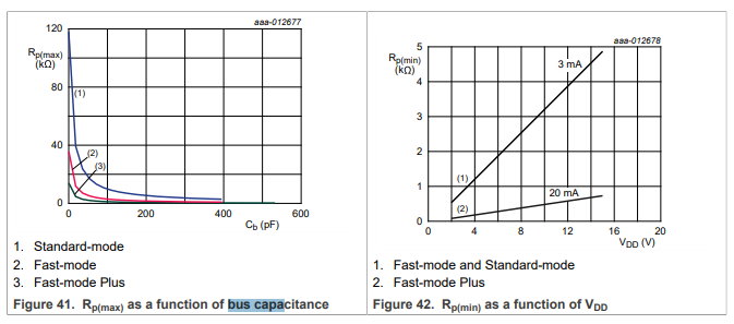
Which should not be a problem, because according to LDC1612 datasheet it should support up to 400kHz.
But there is a capacitor connected to the line with 22nF

Which are out of spec of i2c by orders of magnitude.
About pins, this is really simple.
Code precomputing and saving buses on firmware compilation.
Later they returned to Klipper when MCU connected (just JSON).
So, they are visible in the log.
Any bus from the log, can be specified.
BUS_PINS_i2c1_PA9_PA10=PA9,PA10
BUS_PINS_i2c1_PB6_PB7=PB6,PB7
BUS_PINS_i2c1_PB8_PB9=PB8,PB9
BUS_PINS_i2c2_PB10_PB11=PB10,PB11
BUS_PINS_i2c2_PB13_PB14=PB13,PB14
BUS_PINS_i2c3_PB3_PB4=PB3,PB4
BUS_PINS_i2c3_PC0_PC1=PC0,PC1
pins.py specifically verifies and matches that pins are not used in compatible spaces as best as it can.
From the code side, only those are supported:
#elif CONFIG_MACH_STM32G0
  DECL_ENUMERATION("i2c_bus", "i2c1_PB6_PB7", 0);
  DECL_CONSTANT_STR("BUS_PINS_i2c1_PB6_PB7", "PB6,PB7");
  DECL_ENUMERATION("i2c_bus", "i2c1_PB8_PB9", 1);
  DECL_CONSTANT_STR("BUS_PINS_i2c1_PB8_PB9", "PB8,PB9");
  DECL_ENUMERATION("i2c_bus", "i2c1_PA9_PA10", 2);
  DECL_CONSTANT_STR("BUS_PINS_i2c1_PA9_PA10", "PA9,PA10");
  DECL_ENUMERATION("i2c_bus", "i2c2_PB10_PB11", 3);
  DECL_CONSTANT_STR("BUS_PINS_i2c2_PB10_PB11", "PB10,PB11");
  DECL_ENUMERATION("i2c_bus", "i2c2_PB13_PB14", 4);
  DECL_CONSTANT_STR("BUS_PINS_i2c2_PB13_PB14", "PB13,PB14");
  #ifdef I2C3
    DECL_ENUMERATION("i2c_bus", "i2c3_PB3_PB4", 5);
    DECL_CONSTANT_STR("BUS_PINS_i2c3_PB3_PB4", "PB3,PB4");
    DECL_ENUMERATION("i2c_bus", "i2c3_PC0_PC1", 6);
    DECL_CONSTANT_STR("BUS_PINS_i2c3_PC0_PC1", "PC0,PC1");
  #endif
At least on this specific commit.
TLDR:
Compiled in HW buses depends on MCU.
Only buses which are compiled in can be used.
Naming can be different between different families of MCU.
This is just naming and versions - happens once in a while.
This is complicated stuff to keep everything in sync, moreover past the time.
Your actual firmware and your actual logs right now are a source of truth about available configurations. But limited by actual schematics.
There is a lack of any error handling at that time and now.
So, software can’t actually tell you what is going on here.
MCU code just tries to write/read and return timeouts if something does not work.
(Even if there is error handling, you will only see something like NACK).
You still can just check these specific new lines with oscilloscope, if anything actually happens on them while transmission.
According to schematics, these lines can work.
But I can’t see where you can connect to them, to actually do something.
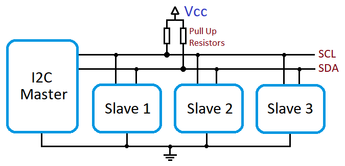
At the start of the topic, I said - use resistors on the sensor side.
It lacks them - add them, that will make your meander more square.
I hope, some of the written above helps.
I understand we’ll be soldering tomorrow)))
Do you think that if i remove the capacitors it will give a result?
or do I need to set a different capacitor rating?
Do you think that if i remove the capacitors it will give a result?
or do I need to set a different capacitor rating?
I can only use schematics and my imagination.
According to schematics, there are inline resistors 1kOm, pull-up 10kOm, and capacitor.
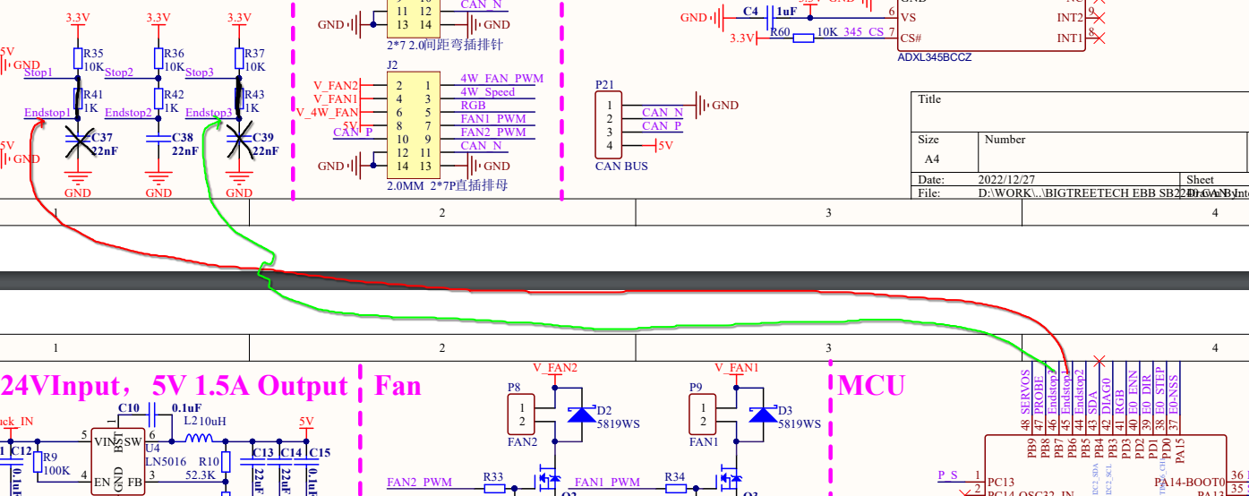
On I2C capacitance should be minimized, as a consequence capacitors should be removed and ground disconnected on SDA/SCL (endstop3/endstop1) (PB7/PB6).
Inline resistors should “not” add/solve a problem, the line is short, so there, I believe - you can just short them.
Pull-ups can be kept in place.
In the end, it will look like a normal i2c bus, it should work.
Ok. I’ll inspect the board tomorrow and start looking for these capacitors!
Thanks for the information!
if we don’t succeed we’ll come back to your advice with the resistors for eddy)
although it won’t take long to add some resistors and check your theory! we’ll check everything tomorrow!)))