I hate saying this yet again but right now the goal should be to get the I2C lines coming out of the P10/P19 connectors wiggling. If you don’t see the lines changing, it doesn’t matter whether or not the capacitors are still in place.
In working through this, I am trying to keep the EBB SB2240 as pristine as possible - no soldering until it becomes obvious. Removing parts or soldering/desoldering has the potential of making things a moving target.
Could we please try to figure out why you’re not seeing anything changing on the I2C lines before touching an iron to the board?
From what I’m seeing in your posts, the specified values (sb2240 and i2c1_PB6_PB7) should be correct.
So why isn’t @borysne seeing any changes in the I2C lines - the RC network on the Stop# pins have a tau of 254ms so even with the capacitors in place, we should be seeing something similar to what @borysne saw from the Manta M8P V2.
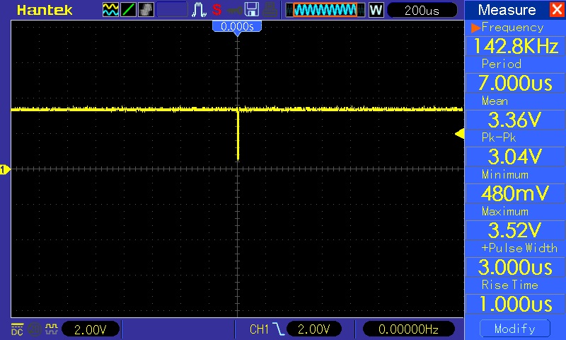
One thing I just realized I should have asked @borysne - what is the trigger level on your oscilloscope you’re using for probing PB6/PB7? Looking at the latest screen shot:
It looks like you’re waiting for a rising edge at 3.6V when you should be looking for a falling edge at something less than 3.3V.
Maybe things are working, but if the trigger isn’t set properly, then we can’t see them.
to implement your idea! I need to connect pull-up resistors to 3.3v. on Eddy Coil but there is nowhere to get it! you can connect to 5v but on the Manta board it is connected to 3.3v. a voltage conflict is possible and how this will affect is unknown
I looked through everything! PB5, PB6 have a capacitor!!!
PB7 no capacitor!
looks like whoever made the board forgot about it)))
or it didn’t fit on the board)))
Okay, time flies
I need to do something! First, I’ll remove the capacitor from the line SCL pin PB6
I won’t touch the 1 kOhm resistor for now! I’ll take measurements and continue!
I looked through everything! PB5, PB6 have a capacitor!!!
PB7 no capacitor!
looks like whoever made the board forgot about it)))
or it didn’t fit on the board)))
I can’t give you any advice other than go through the board with your microscope and your DMM set to check continuity.
When you do your oscilloscope shots in the future, please include both SDA and SCL - it will be important when we’re checking the EDDY Coil communications.
Do you know why I didn’t find it!!!
its installation doesn’t match the diagram!!!
capacitor C39 is installed between GND and pin PB7
according to the diagram С39 should be between the 1k resistor and GND!!!