Hmm, really strange.
When i’m home again, i’ll try to figure it out with an oszilloscope.
Maybe someone has a data analyzer, would be easier.
120ohm resistors on both ends activated?
Hmm, really strange.
When i’m home again, i’ll try to figure it out with an oszilloscope.
Maybe someone has a data analyzer, would be easier.
120ohm resistors on both ends activated?
I have an oszilloscope and a logic analyzer with CAN-bus support ![]()
I will take some measurements next weekend.
I have just measured the resistance between can-H and can-L: 117 ohm on the SKIPR side and 60 ohm on the SHT36 side ![]()
As far as I know is 60 ohm the correct value. The two 120 ohm terminating resistors are connected in parallel and thus form an equivalent resistance of 60 Ω.
Why skipr has 120 ohm between H/L?
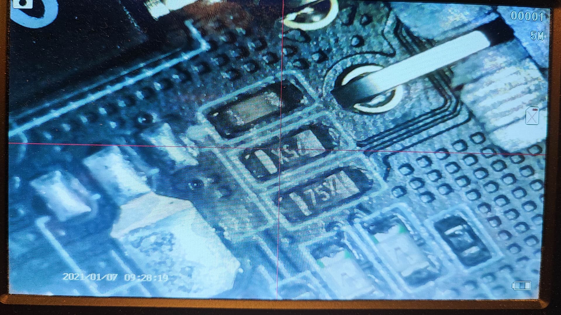
I took a deeper look under the microscope and can say that R265 and R266 are 60 ohm each and connected in series.
Could this be the reason for the malfunction?
I have never worked with the CAN bus and don’t really know anything about it.
Nope, both side should have 120 ohm resistors, when the line is connected, you should measure 60 ohm on each end, like you said equivalent resistorvalue.
If you put two 60 ohm resistors in serial, you’ll get 120 ohm, that’s ok. But why they used two of 60 instead one 120. Maybe they had the 60 loaded in their pnp system and did want to use an extra amount of 120 for only one position
They placed the capacitor at the wrong place ![]()
Who? Mellow or MKS? Could this be the reason?
Mellow, they connected the resistor directly to ground and the capacitor between both resistors.
You need 120 ohm terminator resistors for the bus, this way you won’t get it.
Should be the same like on the mks, the capacitor between ground and both resistors
But i don’t understand why both grounded this parts.
A termination should be only between both data lines, one single 120 ohm.
But on the Octopus it’s grounded too, so this shouldn’t be the problem.
BIGTREETECH Octopus Pro_SCH (1).pdf (363.0 KB)
Okay, but the Mellow works flawless with my RS485 Can Hat on a Raspi Pi ![]()
I found an explanation for that wiring:
"Instead of providing a single bus termination resistor at each of the ends of the communication channel, the ends of the [CAN bus] may be terminated with a split bus termination instead.
A split bus termination, consisting of two identical resistors (60 Ohm) and one capacitor (typically 4.7 nF), acts like a low-pass filter; high-frequency signals are shunted to ground without affecting the d.c. voltage relationships. Measurements have shown that this can improve noise immunity and reduce emissions."
So IMHO it seems to be ok.
Yeah, i think it may work, because the bus length isn’t that long.
But i would recommend only one side to grund, so i myself would short the capacitor on the mellow and cut the ground connection.
Common way in electrical environments to have only one side to ground.
This all sounds good, but the problem persists on different toolheads it seams. SB2040( which has one 120ohms resistor), Fysetc CAN TH, the SHT boards…
I really think the problem is on the SKIPRs side, not the toolheads. (As one can read elsewhere Octopus seems to work with the different toolheads)
Yes, I absolutely agree with you.
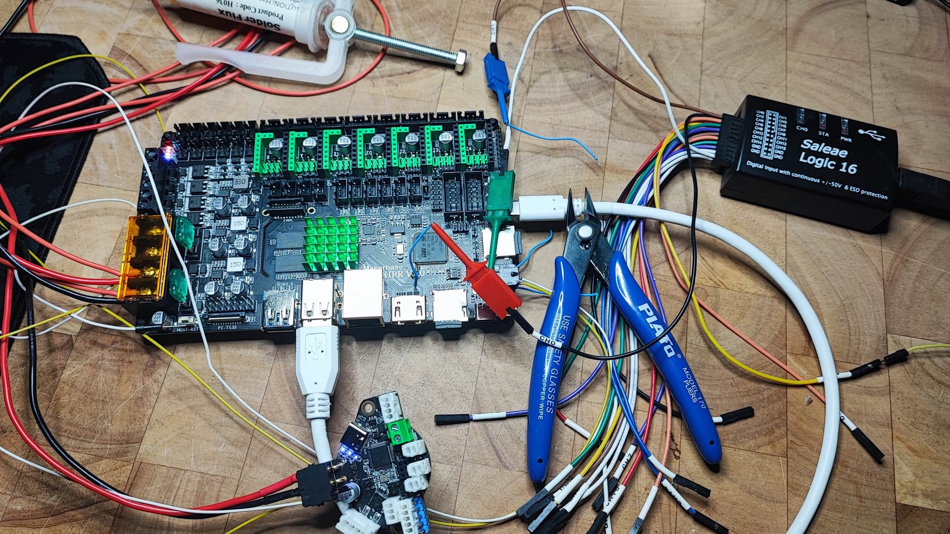
I have hopes that I will find a fault on the Skipr PCB that does not match the schematic. Next weekend I will measure the PCB and also put the logic analyzer on it.
This screams for a live stream ![]()
I know that the resistors shouldn’t be the problem here. It’s only a general consideration for the signaling and interferences.
May I suggest that you read the CAN BUS Specification (especially page 4):
CAN has two floating differential data lines that are terminated at each end. The capacitor between the two 60 Ω resistors is known as a “split termination” and provides reduced emissions as the resistor/capacitor networks form a low-pass filter. This is discussed on page 7 of the TI document linked above.
Yes, grounding only on one side is correct in terms of shielding!
But grounding the capacitors on both sides of the bus has nothing to do with the shielding. So we can disregard that.
In case of the split termination grounding on each side is correct.

Okay guys, because I’m so curious, I started taking measurements today and not at the weekend.
Here is what I have found out:
Here are the measuring points on the circuit diagram:
Test conditions:
As expected, the CAN-H line showed a high signal and the CAN-L line a low signal. However, no data was transmitted and no signals could be measured.
My conclusion:
Either the issue is on the Klipper Software site
or the STM32F446 (Octopus) behaves different to STM32F407 (Skipr)(Klipper driver?)
Other ideas?
Okaaaaay? Nice work dude.
So, than it’s not wondering why we can’t find any devices.
Maybe you can desolder the transceiver or R263 and R264 to get a clear signal without any interferences maybe from there