Surely I could help somehow. On my version of K1, I tried to cut out all the Creality changes in the Klipper code and return the files to their original form. Plus, I managed to dig deeper into their prtouch code before it disappeared from everywhere and began to be distributed only in compiled form, and I had no problems with noise.
By the way, if my memory serves me correctly, @zarboz uses a non-native board with FTDI adapters with buffers, which introduce an additional significant delay during data transfer.
“loadcell” seems nicer to me, but it’s not a big deal either way.
Okay.
For what it is worth, you seem to be describing a scalable config description that seems complex to me. I’d try to keep things simpler - in particular I’d try to code for “what we need now” and not worry about what could “come in a possible future”.
A simpler config (both in new code files and in new user facing config sections) might be something like:
Thus just one new file (loadcell.py) that instantiates an HX71x() class (also located in loadcell.py) and instantiates a loadcell probe handling class (also located in loadcell.py). And, for example, If the user does not specify z_probe_trigger_pressure (or some other appropriate config value) then the code will only instantiate an HX71x() class and not support probing. Thus, for the first PR, we could review and merge just the simplified bulk sensor HX71x() code without probing support.
There are other ways to do this, of course. (For example, [probe_loadcell my_loadcell_probe] for typical probe based loadcells or just [hx71x my_loadcell_sensor] for loadcells not used as probes.) But, I don’t think we want to add 4+ new code files and 4+ new config sections to go along with them. I fear that may be adding complexity before it’s been shown that we need it.
[load_cell_probe]
sensor_type: hx717
dout_pin1: PB9
sclk_pin1: PB8
counts_per_gram: 131.755777
reference_tare_counts: 537140
#counts_per_gram = 131.35294
#reference_tare_counts = 557651
safety_limit: 1000.0
#   The safe limit for probing force relative to the reference_tare_counts on
#   the load_cell. The default is +/-1Kg.
trigger_force: 200.0
#   The force that the probe will trigger at. 50g is the default.
continuous_tare_highpass: 0.8
#   Enable optional continuous taring while homing & probing to reject drift.
#   The value is a frequency, in Hz, below which drift will be ignored.This
#   option requires the SciPy library. Default: None
continuous_tare_lowpass: 100.0
#   The value is a frequency, in Hz, above which high frequency noise in the
#   load cell will be igfiltered outnored. If this option is set,
#   continuous_tare_highpass must also be set. Default: None
continuous_tare_notch: 50, 25
#   1 or 2 frequencies, in Hz, to filter out of the load cell data. This is
#   intended to reject power line noise. If this option is set,
#   continuous_tare_highpass must also be set. Default: None
#continuous_tare_notch_quality: 2.0
#   Controls how narrow the range of frequencies are that the notch filter
#   removes. Larger numbers produce a narrower filter. Minimum value is 0.5 and
#   maximum is 3.0. Default: 2.0
continuous_tare_trigger_force: 100
#   The force that the probe will trigger at whe using the continuous tearing
#   filter. 40g is the default.
#tap_filter_notch: 60.0
#tap_filter_notch_quality: 2.0
#   Filters the load cell data before the tap is evaluated. This option may
#   provide marginal accuracy improvement when notch filtering at the mains
#   power frequency. Requires SciPy. Default: None
#trigger_count: 1
#   The number of samples over the trigger_force_grams threshold that will cause
#   the probe to trigger. 1 is the default.
#pullback_dist: 0.1
#   The distance of the pullback move in mm. This move needs to be long enough
#   to bring the probe away from the bed after it makes contact.
#pullback_speed: 0.4
#   Speed of the pullback move. The default value is to move at a speed of 1
#   sample every 1 micron based one the sensors sample rate is.
settling_time: 0.375
#   Additional time to wait before taring the probe. This allows any vibrations
#   to settle and bowden tubes time to flex etc. This improves repeatability.
#   If the continuous_tare_filter is used this may be set to 0.
#pullback_extra_time: 0.3
#   Time to collect additional samples after the pullback move ends in seconds.
#   This improves accuracy by giving the algorithm more points after the probe
#   breaks contact with the bed. Disabling this entirely may impact reliability.
#tare_count: 16
#   The number of samples to use when automatically taring the load_cell before
#   each probe. The default value is: sample_per_second * (1 / 60) * 4. This
#   collects samples from 4 cycles of 60Hz mains power to cancel power line
#   noise.
#bad_tap_module:
#   Name of a printer object that implements the BadTapModule interface. This
#   checks taps to see if they meet minimum requirements and can
#nozzle_cleaner_module:
#   Name of a printer object that implements the NozzleCleanerModule interface
#   than can handle nozzle cleaning. If one is provided the nozzle_cleaner_gcode
#   is disabled.
#nozzle_cleaner_gcode:
#   A Gcode macro that is called when a bad tap is detected and the nozzle needs
#   to be cleaned. The default Gcode prints a warning to the console.
z_offset: 0
speed: 2
samples: 3
sample_retract_dist: 2
lift_speed: 2
samples_result: median
#samples_tolerance:
#samples_tolerance_retries:
#activate_gcode:
#deactivate_gcode:
This is the result:
 13:32:20  $ PROBE
13:32:22  // probe at 250.000,250.000 is z=1.751975
13:32:26  // probe at 250.000,250.000 is z=1.751299
13:32:30  // probe at 250.000,250.000 is z=1.751461
13:32:30  // Result is z=1.751461
LOAD_CELL_DIAGNOSTIC output:
 13:37:31  $ LOAD_CELL_DIAGNOSTIC
13:37:31  // Collecting load cell data for 10 seconds...
13:37:41  // Samples Collected: 3029
13:37:41  // Measured samples per second: 303.4, configured: 320.0
13:37:41  // Good samples: 3029, Saturated samples: 0, Unique values: 1035
13:37:41  // Sample range: [3.18% to 3.20%]
13:37:41  // Sample range / sensor capacity: 0.00861%
One thing I noticed: My bed is kind of heavy. I have a 355x355x8mm aluminum buildplate. If I put my cup of coffee on my table, i can see it on the loadell output. I think the bed acts like a seismic mass turning the loadcell in an erthquake detector.
I had to lower the speed and put the trigger force up because I think the inertia of the bed already caused a trigger…
But its already really nice. Did not expect to come this far in that short amount of time
This is awesome! That is a whole lot of vibration (80g?!). And it works with inverted polarity! I never got the chance to test this, but I coded for it, so I’m really happy it worked
Under a micron probe-to-probe!
Why 25hz?
I need to work on the diagnostic tool so its easier to copy the data from a probe into the notebook to to the analysis (like a link or button under each graph that copies the python to the clipboard). I’d live to drop this into the notebook and see if there are better settings for this printer.
That was just me trying out some values, I guess I forgot to remove it afterwards. I think i misinterpreted vibration as noise.
Also worth to mention that I used screened cable (actually I cut open an old usb cable) from sensor to all 4 load cell. At first I connected the screen of the cable with the grounding connection (aka earth connection or PE of the printer) - that resulted in terrible noise (± 60g). So I connected the screening to the negative terminal of the 24V power supply and that removed a lot of noise.
I used unshelled twisted pair Ethernet cable on my test rig and that improved things quite a bit. I still don’t think we, as a community, have a good formula for grounding and noise isolation yet.
What microstep rate are you using on Z? Is there one that is quieter/smoother?
As it turned out, neither 16 nor 32 made a big difference in microsteps. It’s not that bad, i just had to raise the limits for triggering a bit. Also, trigger_count: 2 seemed to help a lot, since my vibrations are not one constant foce above 0 - its alternating. Currently this is working for me
[load_cell_probe]
sensor_type: hx717
dout_pin1: PB9
sclk_pin1: PB8
counts_per_gram: 131.572479
reference_tare_counts: 535359
# counts_per_gram: 131.862920
# reference_tare_counts: 538375
# counts_per_gram: 131.755777
# reference_tare_counts: 537140

safety_limit: 1500.0
#   The safe limit for probing force relative to the reference_tare_counts on
#   the load_cell. The default is +/-1Kg.
trigger_force: 250.0
#   The force that the probe will trigger at. 50g is the default.
continuous_tare_highpass: 0.8
#   Enable optional continuous taring while homing & probing to reject drift.
#   The value is a frequency, in Hz, below which drift will be ignored.This
#   option requires the SciPy library. Default: None
continuous_tare_lowpass: 100.0
#   The value is a frequency, in Hz, above which high frequency noise in the
#   load cell will be igfiltered outnored. If this option is set,
#   continuous_tare_highpass must also be set. Default: None
continuous_tare_notch: 50
#   1 or 2 frequencies, in Hz, to filter out of the load cell data. This is
#   intended to reject power line noise. If this option is set,
#   continuous_tare_highpass must also be set. Default: None
#continuous_tare_notch_quality: 2.0
#   Controls how narrow the range of frequencies are that the notch filter
#   removes. Larger numbers produce a narrower filter. Minimum value is 0.5 and
#   maximum is 3.0. Default: 2.0
continuous_tare_trigger_force: 230
#   The force that the probe will trigger at whe using the continuous tearing
#   filter. 40g is the default.
#tap_filter_notch: 50.0
#tap_filter_notch_quality: 2.0
#   Filters the load cell data before the tap is evaluated. This option may
#   provide marginal accuracy improvement when notch filtering at the mains
#   power frequency. Requires SciPy. Default: None
trigger_count: 2
#   The number of samples over the trigger_force_grams threshold that will cause
#   the probe to trigger. 1 is the default.
pullback_dist: 0.2
#   The distance of the pullback move in mm. This move needs to be long enough
#   to bring the probe away from the bed after it makes contact.
#pullback_speed: 0.4
#   Speed of the pullback move. The default value is to move at a speed of 1
#   sample every 1 micron based one the sensors sample rate is.
settling_time: 0
#   Additional time to wait before taring the probe. This allows any vibrations
#   to settle and bowden tubes time to flex etc. This improves repeatability.
#   If the continuous_tare_filter is used this may be set to 0.
pullback_extra_time: 0.3
#   Time to collect additional samples after the pullback move ends in seconds.
#   This improves accuracy by giving the algorithm more points after the probe
#   breaks contact with the bed. Disabling this entirely may impact reliability.
tare_samples: 20
#   The number of samples to use when automatically taring the load_cell before
#   each probe. The default value is: sample_per_second * (1 / 60) * 4. This
#   collects samples from 4 cycles of 60Hz mains power to cancel power line
#   noise.
#bad_tap_module:
#   Name of a printer object that implements the BadTapModule interface. This
#   checks taps to see if they meet minimum requirements and can
#nozzle_cleaner_module:
#   Name of a printer object that implements the NozzleCleanerModule interface
#   than can handle nozzle cleaning. If one is provided the nozzle_cleaner_gcode
#   is disabled.
#nozzle_cleaner_gcode:
#   A Gcode macro that is called when a bad tap is detected and the nozzle needs
#   to be cleaned. The default Gcode prints a warning to the console.
z_offset: 0
speed: 2
samples: 1
sample_retract_dist: 0.5
lift_speed: 2
samples_result: median
samples_tolerance: 2
samples_tolerance_retries: 2
#activate_gcode:
#deactivate_gcode:
But I had to notice that “pullback_dist” did not have any effect on the actual pullback. The problem seems to be line 781 on load_cell_probe.py where you overwrite pullback_distance with 0.1:
self.pullback_distance = 0.1
although the parameter in the config is named “self.pullback_dist”. I fixed it by replacing line 781 with
Accelerometers can in principle be used, but not as detection of the acceleration, rather by integrating the values provided in relation to the commanded speed, so that you can estimate when a delta between commanded and obtained motion arises.
I was hoping to do something scalable especially for the sensor because they don’t need to be associated with load cells (maybe like /klippy/extras/sensors). But I will put them in 1 file and you can re-organize it later. It looks like it will be the largest extra as of right now, larger than bed_mesh.
Its going to take me a few weeks to find the time to do the refactoring we have discussed and get the PR out.
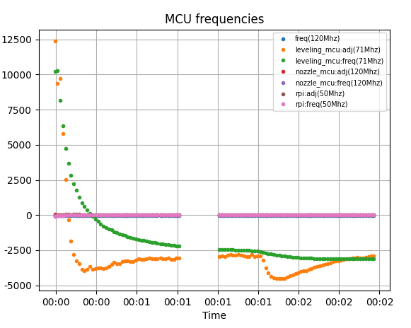
Just a note that we are making some headway with the Creality K1. Initially it was behaving in a way that was absolutely bizarre and I suspected that the MCU timer was unreliable. This was traced to incorrect implementation of the timer in the GD32 code and verified using graphstats.py to show clock drift under load:
@ZeyHex and I managed to re-write the timer initialization routine and configure the GD32 chips to implement capture & compare based timing like STM32. this fix 100% works. The bad news for K1 owners is that all of the MCUs need flashing to fix this. Time is position, accurate time is critically important.
Once we solved that we had fits trying to get rid of apparent “ESD noise” on the sensor chips. This appears to be due to not reading the sensor for extended periods of time. If an hx71x chip goes unread for more than 1 sample period it seems it can flip bits on a subsequent read. I was able to reproduce this on the HX717 by trying to read it at 80SPS:
The timer/IRQ code we already have is sound so there wont be any changes for the single sensor version. But for the 4-sensor version we have to read every sensor that is ready immediately and save its reading. Then readings are reported to the host only when the first sensor reports that it has a sample ready. This makes the board appear the be a 4-channel synchronous sensor with the clock locked to the first sensor.
With a bit more debugging and configuration changes (this printer needs extra pullback_dist) we were able to get a PROBE_ACCURACY result with a range of 0.0037mm (3.7 microns). This is a pretty encouraging result given the slow sensors and oversized load cells. Huge shout out to @ZeyHex for the tireless debugging to get here!
We are still working through some gremlins. Most recently a “Timer too close” error on the main MCU. But I expect that we will get it to work soon…
Soft Elbows
We did find one issue with the algorithm that needs work. The K1 doesn’t have a high absolute peak force when the probe stops moving down. Maybe this is due to the low sample rate:
(Here the peak force is actually a noisy point far right of the elbow)
The current code looks for the peak force and expects that point to be the second elbow in the plot. It checks that the peak force is close to the blue line (trigger time) and will reject the probe if it is now. I’ll have to work on a strategy for finding this “soft” elbow that is more robust. (I have good elbow finding code I just need to use it here)
ADS1220
Separately I’ve also been working on sensor code for the ADS1220. It is a good HX717 alternative with faster sample rates (up to 2Khz) and hardware SPI. It’s also in the JLCPCB parts bin making it a good target for prototyping boards. It’s not everything you could want, the SPI speed is slow (just 512,000 in turbo mode) and there is no power reset notification. But it would work well in a tool board.
@garethky (and team) Thanks for your awesome work!
Ignore my deleted posts, still learning the editor
Similar on the CR10 SE, with a fancyCRTENSE_NOZZLE_CLEAR macro in z_compensate.py. Which they also closed and compiled with the official “Open Source” release on Monday.
It does the hot_rub_temp wipe at 200 in a reserved space on the bottom left of the plate, at random Y positions . Then leaves the nozzle at hot_end_temp for the probing with bed_add_temp at 60. Also at random X/Y positions near Z Home.
For heat expansion, they seem to just subtract a tri_expand_mm of 0.07 from the final zoffset to compensate.
The pin swap is also interesting.
How can I share the code? I have a copy of their z_compensate.py and [z_compensate] section of printer.cfg - with comments which I translated from Chinese…
The PR to open up prtouch_v2 does not seem to go anywhere:
The extruder PCB has a LED which lights up with the slightest movement of the nozzle. Even the noisy fan triggers it. So I guess the MCU reads the sensor constantly.
And how can I contribute with testing?
I currently get exactly the 0.065mm variance from the hx711.
The CR10 SE has the nozzle mounted on one load-cell.
I realise now the Nozzle MCU would probably also have to be flashed. And I do not have spare MCU. It is a GD32F303CBT6.
To make it worse, I see now it does not have a dedicated levelling MCU like the K1
I guess because the MCU is already in the toolhead, close to the cell.
And Creality will probably put up a fight for the source code.
PS: The Ender 3 KE has a single load-cell in the front left corner. With a (I guess) HX711 board close to it. There seems to be no MCU that offloads the processing.
Hello!
im currently desiging a toolhead for my printer and i got a bit confused, is the support for ADS1263/ADS1255 discontinued completely? And all the new updates are for HX717/HX711? or would the ADS1263/ADS1255 still be beneficial and possible to use? currently it seems ADS1263/ADS1255 is more readily available compared to HX717 (from digikey/farnell/tme/mouser atleast) price is a bit crispy at 18€ per IC for 63 and 55 13€ but if it would make homing faster/more reliable then that seems worth it?
I used the ADS1263 as a prototyping sensor because it was available as a ready built board and it has a lot of features that I could explore. Turns out most of those features aren’t very useful for this application. But one thing it’s missing is useful: a 128 PGA gain setting. Its also too expensive and too large to put on a toolhead board.
We have been looking at the JLCPCB available parts list as a proxy for what we might see in the market. I’m adding support for the ADS1220 because it’s a good match to the capabilities and price of the HX717 but with faster sample rates, SPI and a smaller physical footprint (VQFN-16).
I’ve tried to do this and I am not happy with the resulting ~3K line file. That’s not something I want to work on or maintain. I’d like to talk alternatives:
I’d like to put the sensors and sensor interface in separate files. We both seem to agree that they should be re-usable by others for new extras. This is the pattern for other sensors in the code base; each sensor is in its own file.
I understand your desire to keep things organized limit the clutter in the /extras directory. So how about using a sub-directory, /extras/bulkadc/, to keep the sensors and sensor interfaces in one place? Then its clear they are related but its also clear how to add a sensor without editing a file called loadcell.py. Its also possible to import the sensor interface and support code without running into circular dependency issues. The sensors don’t have to be something you can create from config, that’s fine by me.
Adding sensors is not hypothetical, I am working with other contributors that are actively adding more sensor support. They are in agreement with me that the current organization with sensor in separate files is much easier for them to work with. They don’t have to worry about merging their sensor code into a large shared file. In the case of long running forks, e.g. for Creality machines, its much easier to merge changes from klipper mainline if they are not in a single file.
Okay. Please consider all my comments here and previously as “high-level thoughts”. I don’t know the loadcell code enough to make detailed judgement calls on the code layout.
That’s possible, but for what it is worth, I think we can trivially create that directory after the 3rd or 4th sensor. So, I’m not sure we should create that directory before we’ve even added the first sensor. I don’t see an issue either way though.
For what it is worth, that was the main idea I was trying to convey in my previous message (try to keep user facing configs simple). I agree it’s generally not a good idea to put lots of functionality into a single .py file. Sorry for the confusion.
Separately, it would be great if we could start merging in the sensor code. That’ll make it easier to review and I think it may also make it easier for me to provide better feedback.
Ok great. I wasn’t sure if you wanted me to just do or if you were open to the feedback.
This is the same pattern I’m following, should look familiar in a PR.
I will try to get the 2 sensors out for PR this weekend. All of the other stuff that we discussed has been done. I’ll leave off merging the load cell and the probe objects together until we get to the last PR. I think we might come to the conclusion that its too much code to put in 1 file.