What do you think about the load cell used in the cr 6 se
10$ but not too small …
What do you think about the load cell used in the cr 6 se
10$ but not too small …
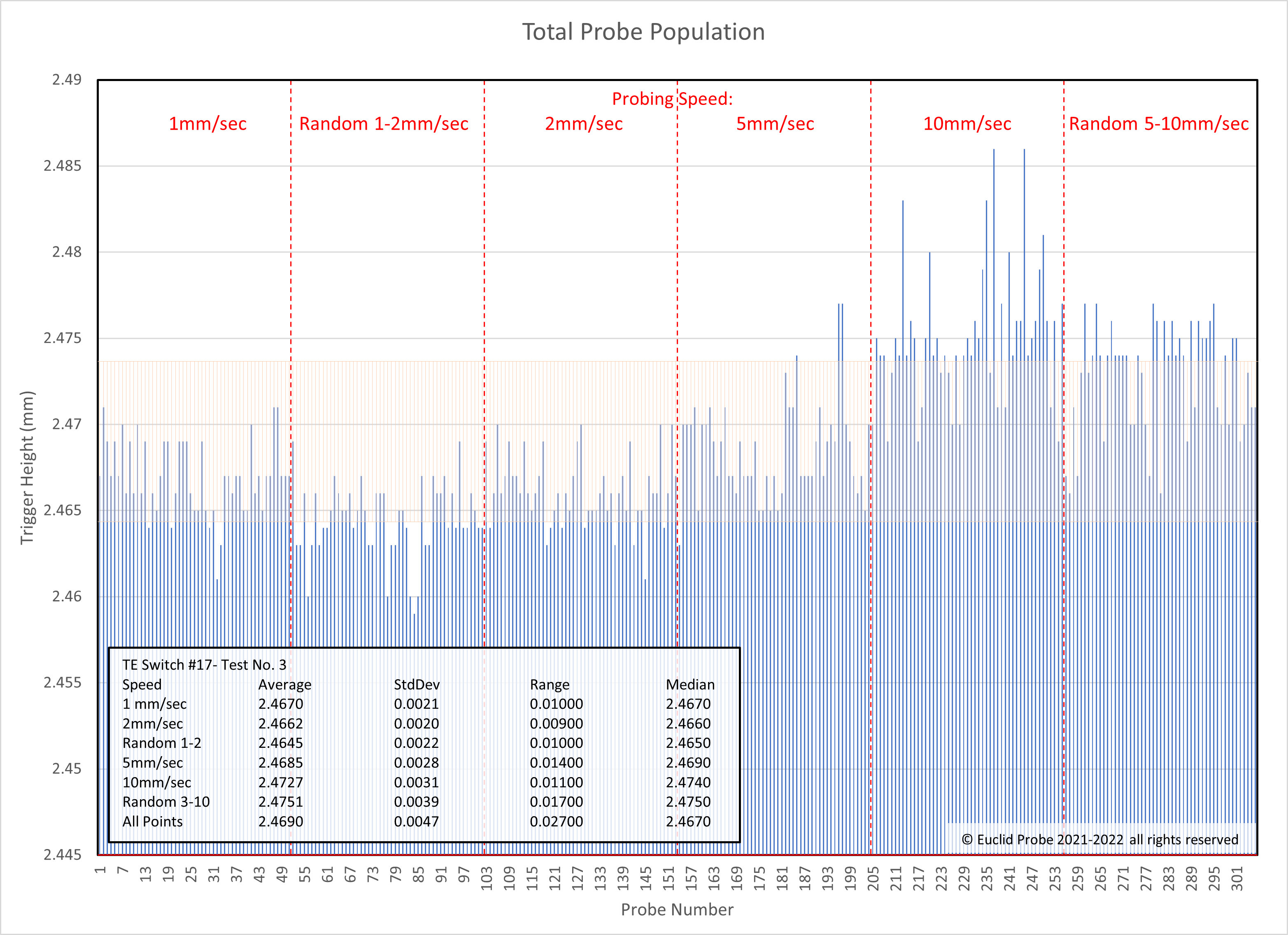
Something I have been meaning to do for a while is replicate Euclid’s accuracy testing results: Euclid Probe Accuracy | Euclid Probe the highly accurate detachable Z-probe for your 3D printer, laser and CNC see their graph here: https://euclidprobe.github.io/images/00-ProbeTest57_19_45-768x559.png
Their methodology is to do batches of 50 probes at various speeds. I had to do a modified version of PROBE_ACCURACY to do the randomization for the tests where its a speed range.
Here are the results:
| speed | maximum | minimum | range | average | median | standard deviation |
|---|---|---|---|---|---|---|
| 1mm/s | 0.0172 | 0.0106 | 0.0065 | 0.0117 | 0.0116 | 0.0010 |
| 2mm/s | 0.0136 | 0.0069 | 0.0067 | 0.0097 | 0.0098 | 0.0010 |
| Random 1-2mm/s | 0.0098 | 0.0066 | 0.0032 | 0.0078 | 0.0077 | 0.0007 |
| 5mm/s | 0.0026 | -0.0036 | 0.0062 | -0.0015 | -0.0018 | 0.0013 |
| 10mm/s | -0.0104 | -0.0167 | 0.0063 | -0.0139 | -0.0137 | 0.0014 |
| Random 5-10mm/s | -0.0093 | -0.0153 | 0.0059 | -0.0123 | -0.0123 | 0.0014 |
Euclid has an average range of ~0.01mm, load cell range is ~0.006mm in these tests. I think these results represent “real world” conditions, with a clean nozzle against a PEI build sheet. They are not idealized or cleaned up. There were, in fact, outlier points in the data that drove up that range, especially for the 1mm, 2mm and 5mm tests:
That means you get micron level accuracy in just 1 probe. When the probe is “wrong”, its a rare event and its wrong by less than 1/2 of Euclid’s error.
Over 50 probes we start to see some things that you probably wont notice in real use. Looking at the data you might ask:
Well, the harder you hit the bed, the more deformation you cause to the toolhead. There is some hysteresis so the toolhead doesn’t come back to its original shape instantly when it clears the bed. This is why faster probes result in lower Z values. Faster probes make the toolhead shorter.
So what we are actually seeing over the full speed range is the hysteresis of the toolhead. This toolhead has 0.03mm of hysteresis over the force range which is about 100g to 1.5kg.
As to question #2: range over 10 probes often approaches 0.001mm, a full order of magnitude better than Euclid:
10:46:05  // PROBE_ACCURACY at X:150.000 Y:125.000 Z:0.522 (samples=10 retract=0.500 speed=5.0 lift_speed=10.0)
10:46:07  // probe at 150.000,125.000 is z=0.016213
10:46:10  // probe at 150.000,125.000 is z=0.016564
10:46:12  // probe at 150.000,125.000 is z=0.016197
10:46:14  // probe at 150.000,125.000 is z=0.016494
10:46:16  // probe at 150.000,125.000 is z=0.016319
10:46:18  // probe at 150.000,125.000 is z=0.015925
10:46:20  // probe at 150.000,125.000 is z=0.016219
10:46:22  // probe at 150.000,125.000 is z=0.016252
10:46:24  // probe at 150.000,125.000 is z=0.015641
10:46:26  // probe at 150.000,125.000 is z=0.015380
10:46:26  // probe accuracy results: maximum 0.016564, minimum 0.015380,
 range 0.001185, average 0.016120, median 0.016216, standard deviation 0.000351
But even in that smaller sample size there is a tend to lower Z values:
I assume the physical system doesn’t have time to fully relax between probe cycles with PROBE_ACCURACY hammering away in one spot. The test sets with random speeds don’t have this pattern because the slower probes give the toolhead more time to recover. In a real application, like bed_mesh, there is transit time between probes and this is less of an issue. But YMMV based on the physical characteristics of the toolhead and motion system.
How good is the load cell probe? Well its the best probe I have ever used but I might be biased. ![]()
In a real printer, doing a real tasks like bed mesh, I would be comfortable saying 6 microns of range is achievable. That is half of Euclid.
But crucially, probe-to-probe repeatability is sub micron. That’s more than good enough not to need multiple probes. That’s not the way Euclid behaves. Switch probes are very random, each probe might vary by 0.01, so multiple probes are needed for an average. Load cell is usually better than 0.001 on the next sample.
I have been talking to @koconnor about how to move this into PR. We have agreed to break it up into at least 3 parts:
[load_cell][load_cell_probe]We can start on the HX71x bulk sensor PR almost immediately. This will give us some time (several months?) to keep testing and refining [load_cell] and [load_cell_probe].
Before we start the first PR, I want to get some feedback from the community on that overall structure.
My goal fro the start (see thread title) is to make it easy/low code to add more sensors to klipper yb putting the endstop code into a separate object. So I have implemented the “LoadCellEndstop” as a separate component on the MCU with its own set of commands. Sensors that want to support homing only have to do 1 thing: forward their readings to the endstop on the MCU via a function call:
load_cell_endstop_report(lce_oid, ticks, counts);
For this to work two things have to happen:
oid of the LoadCellEndstopThis is a circular dependency that we have to resolve. We have to agree that one of the objects gets initialized first. That has to be driven by where the sensor is physicaly connected, i.e. the MCU. Kevin and I generally agree on this flow:
load_cell_probe (this is how [resonance_tester]'s accel_chip option works):adc_chip: hx717 my_probeload_cell_probe, similat to how [sensor_angle] works:acd_type: hx717 #... +pins and other sensor config etc.[load_cell_probe] passes the sensor to the LoadCellEndstop constructorsensor.get_mcu() to get the MCU of the sensoroid on the sensor’s MCUsensor.setup_homing(oid) on the sensor to tell it about the endstop.oid an additional parameter to its sensor_query command and pass it when measurements are started.setup_homing command to send the endstop oid to the sensor on the MCUOverall we think this is the simplest the flow can be and the one with the loosest coupling. I’ve tried it a number of other ways and not liked the results (including the way thats in the codebase now). As long as we agree on the flow we can ship PRs and everything will fit together. If we change the flow we would probably have to make breaking changes to config.
Given the above plan I have some observations & questions and want feedback:
load_cell_endstop on the MCU, because it wont be part of the PR. So this means the protocol will have to change in a successive PR (either adding a parameter/6.1 or a new command/6.2). I don’t think this is avoidable, because other protocol changes will be needed to support the endstop, but I’m open to ideas.[hx717] and [hx711] config sections. That works well with 1.1, but if you preferred 1.2 then this will become vestigial config after [load_cell] ships. Personally I prefer the pattern in 1.1, its much more flexible long term and allows multiple object to use the same sensor later (e.g. extrusion pressure logging could be separate). But klipper more frequently follows 1.2.bulk_sensor and load_cell_endstop. We don’t think we should ship something which wont be used. Does anyone feel strongly that this should stay in? People with multiple under-bed sensors?Foremost, big kudos and respect that you have driven this across the finish line so diligently and persistent. Chapeau!
For all your questions about the inner workings, I do not feel myself in a position to participate in any meaningful way.
Just one comment:
Does this align with Kevin’s development goals, in particular the rework of the probing and homing commands?
Your explanations sound as if the described concepts could (should?) be carried over to a broader scope, e.g. probing in general (agnostic of the probe type) or even sensorless homing (strange name anyway, since it uses the stepper driver as sensor).
Hey Garethky.
Thanks for all the work you put in.
I want to pitch in after reading silently for a while.
While i don’t have a great amount of expertise to offer on the design for the klipper, my position on the multi-chip issue is as follows:
For a large amount of printers, and especially those using multiple load cells under their bed, weight and integration into a toolhead MCU are not really considerations.
I myself have chosen to go the route of a Pi Pico hooked up to my ADC running my own C Code to simply emulate a clicky probe on an endstop input for klipper. Less complexity for Klipper, and easy to implement. This also makes it firmware/MCU agnostic, yay.
Your goal was to implement toolhead load cell sensors in a non hacky elegant way, and i feel you’ve mostly reached that goal. under bed load cells are different enough in their quirks and issues that i feel they shouldn’t be the focus of this implementation.
I’m very unlikely to ever code around it, but i am slightly partial to 1.1 ![]()
Keep the good work up!
Have Peopoly given any insight into the workings of their loadcell work for the Magneto X? Is it again something with an off-board handling similar to @peterohm or is it something (once publicly available) to take into consideration?
I haven’t seen any communications from Peopoly. I have seen Teaching Tech’s video where they sent out the “upgraded” load cell. PROBE_ACCURACY range is 0.02 @ 1mm/s:

That is just under the 0.025mm bar for a usable probe, 2x worse than Euclid, 20x worse than my implementation. Linear regression of the collision was able to get me under 0.01 @ 5mm/s, but that requires deeper klipper integration. So my current guess is they are doing some sort of off pin triggering, similar to what @peterohm described above (emulating an endstop switch). It’s easy to get up and running but hard to make fast & repeatable.
I havent gotten to try my approach yet, but i’m hoping it’ll be better than 0.02 ![]()
I’m using a TI ADS1256, which is nice, because i can go up to 30k SPS at 24bit resolution and 64x gain. Currently i think I’m testing with 1000 SPS, which should already give me good latencies, but i might go higher if im unhappy. Then again the better way to lower latency would be firmware integration with klipper instead of trying to shrink an already pretty low latency from the Pico. I just think it’s easier for me to do my under bed multiplexing and math on my own in C.
@garethky Do you have any numbers on how much slower klipper catches a emulated endstop setting an endstop pin is vs. a firmware one? (assuming there is no latency incurred by i. e. pi pico)
Thank you! ![]()
Kevin mentioned this. He has a long list of pain points with the existing probing code.
I had to override its internals in 2 places. _probe() and probe(). In pything nothing is private, but by convention methods with names starting with _ are to be treated as private. So I have “done abad thing”, but its the only way to get it to work currently.
I had to override these methods to get the pullback move executed and the final Z coordinated calculated before _probe() returns a result. Generally speaking there is no way to add moves to the Probe sequence without overriding _probe. Low speed pullback moves might be generally useful on other kinds of probes, e.g. switch probes. So maybe this could be generic.
I also had to change the way that “bad taps” were handled and contributed to retries. It’s a value thats so bad that we don’t want to report a number. Probe cant handle that either.
I’m hoping that Kevin gets a chance to look at these use-cases before he refactors but we haven’t had a chance for a deep look at that yet.
I believe klipper samples the pin at the microstep rate? (I’d have to read the code to double check)
Example: The Voron 2.4 has 5:1 gearing, 200 step motors and 32x microstepping. So to move the output 1mm its 200325 = 32Khz. There will be some delay between when you trigger and the next microstep, depending on the step rate. Higher microstepping would be better for this.
With the pullback move I am moving at 0.001mm per sensor sample. Because of the linear regression the precision is the theoretically infinite. The speed is 0.32mm/s.
Moving that slow reduces electrical and mechanical noise significantly. The noise floor limits how quickly you can trigger. The sensors have more noise the higher the sample rate is (internally they run at the max rate and average multiple samples for slower rates). So going fast is going to cost you accuracy in multiple ways. If I could run the sensor on a battery and have it electrically isolated, that would help. But I would still probably pick a sample rate around 5Khz to probe at 5mm/s for the lower sensor noise and run the most microsteps I could to improve triggering latency.
This is awesome!
I was looking for load cells and how to design a toolhead (eg EVA) to adopt one.
But, it’s hard and probably lead to issues down the line (luckily I don’t make a living with my subhuman CAD designing skill), so I’ve taken a step back to my original idea of using the accelerometer data to detect nozzle-bed “collisions”.
So, I’ve read the code in your branch, and I realised you basically don’t use any physical pins on any MCU to trigger the end stop (something I was wrapping my head around).
And I am really glad I read up your code, as I think something like that could be used as a template to filter and normalise the adxl raw data and detect a change point in the resonance or spikes in the accelerometer data (there is a tap functionality, but it’s not wired in in most toolhead board).
Have you ever considered the accelerometer as a potential homing sensor? and if not, any obvious reasons?
Using the adxl would definitely be a really convenient idea. It was explored somewhat in this thread.
I had not thought about it. I saw some video of someone (perhaps it was you!) trying to get tap detection to work on the ADXL. It was violent! I think the probe was at 20mm/s??? My z axis wont even move that fast.
So the questions I have are:
As for code: on the MCU, most of the code doesn’t care about the data being fed in. Its just raw ADC counts, it could be voltage, force or acceleration, it does not care. It just sets a 0 reference and triggers if it sees any value outside of a +/- threshold. It was my original hope that any analog sensor could be used to trigger this endstop.
But the filter does care. Its in fixed point math and it has a specific ratio of integer to floating point bits: Q12.19. 12 integer bits gives us a max force of +/-4096g. 4KG seems like 2x more than we should ever need for a load cell. We want the maximum number of fractional bits because all of the filter coefficients are smaller than 1.
For acceleration data you need to divide the input values by some constant factor to scale them down in magnitude. This is whats going on when I convert counts into grams for the filter code. You can use the python notebook in scripts to experiment with filtering the acceleration data. You probably need some high frequency filtering.
We may end up splitting the filter out into something like the bulk_sensor object that’s reusable. But that will have to wait for the blessings of reviewers.
There was a first attempt few years back, with a klipper feature request. I wouldn’t call it a total failure; progress was somehow shown and it seems someone used it with some success -pre multi-mcu homing-, but it eventually slowed down and than was forgotten. I was surprised nobody brought this up for a definitive yes or no feasibility answer .
Recently there has been further development using the ADXL345 present in CAN boards. There is the fly-STH36 v2 that actually has the INT1 pin connected to the MCU (INT1 and INT2 are the ADXL tap pins), while someone else had luck with the EBB36, soldering a wire from the ADXL to the MCU chip.
I am following various sources on the topic, and I’m not convinced the built in tap it’s solid enough to trust to go about unattended. The principle is very simple, set some param (speed, duration, treshold) and trust the built in tap implementation to detect a signal.
I haven’t done it yet, but on the DELTA2 discord channel, some user got promising results, quoting -not mine-:
probe accuracy results: maximum -2.307500, minimum -2.317500, range 0.010000, average -2.312125, median -2.312188, standard deviation 0.002456
The issue is that by looking at the accelerometer data plots, you can always spot the taps, but the ADXL built in functionality misses it at times. To make things worse, the signal is stronger at high acceleration, but it taps harder, while if you want to be safer it might not detect it at all. It’s not very safe yet imo.
The force applied to the bed -or actually a scale on the bed- (again reporting a summary of what I’ve seen, not my direct experience), is between the 50 and 200 grams.
In my opinion, having a more powerful module that evaluates the signal could really make it more reliable and it will be available to most printers using canbus boards without specific hardware modification.
Plus it could open up to experimentation on the algorithms transformation/normalization.
I have no idea if it’s a stupid concept, but maybe: if the toolhead or the bed or just the extruder resonate to a sweet-spot frequency, when touching the bed the resonance would change so much that the signal would be hard to ever miss even at low speed. And this is not possible to experiment with the current adxl-tap
Hi,
I have some high-level thoughts. Don’t take any of my comments “too seriously” as I don’t know the intricate details of loadcells.
Just out of curiosity, what are “ticks” and “counts”? I’d have thought simply loadcell_report(lce_oid, value) would be sufficient.
I’d say the 1.2 method seems preferable.
I’d say 6.2 is preferable. There are use cases for obtaining the sensor data outside of homing - for weighing filament, for sensing filament extrusion pressure, for gathering bulk data for offline analysis with the “motan” system, and others. It seems more clear to me to logically separate the act of of querying from the act of enabling additional homing checks.
I’d say add the new “hx71x_setup_homing” command in the subsequent PR that adds loadcell homing support.
Yes. It can just be available via the API server (as other bulk sensors are). I don’t see an issue with having an available [hx71x] config section that is rarely used. If you want, you can put the hx71x python class in a new loadcell.py file (eg, [loadcell mysensor]) and just have some mechanism to declare a loadcell that isn’t used for probing (eg, by not declaring a z_offset in the section)
On the topic of config section naming, I’d probably go with [probe_loadcell mysensor] or [loadcell mysensor] (but not both). If you want probe in the name, I think it’s a little nicer to put that “category” information in the front of the name (for better sorting).
For what it is worth, I think we should keep it simple to start - one oid per sensor. If we need some “multi-sensor” capability in the future then I think we should look to add that in the future.
-Kevin
I don’t think this will be an issue. I suspect that development goal of mine will follow loadcells, not the other way around.
I suspect we’ll need to refactor the probing code (both for loadcells and for ldc1612 chips). I’d say lets merge in the hx71x support first, then we can look at the probing needs of loadcell, then we can work on refactoring the probe code, and then we can merge in the loadcell probing code on top of that.
At a high-level I think we need the main probing code (as located in probe.py) to support a sensor specific “probe()” mechanism that returns the measured bed Z position at the given XY position (as opposed to the current code which assumes the toolhead descends and assumes the bed Z position is related to the final toolhead position).
-Kevin
As Peopoly has described it to me, their loadcell implementation is effectively a separate piece of hardware wired as a kind of “endstop” (that is, it signals a contact via a standard gpio pin that Klipper checks). Similarly, in case anyone is curious, their linear motor drivers as described to me are also effectively separate hardware controlled via standard dir/step signals.
Cheers,
-Kevin
I’m fine with most of your comments. I want to respond to just a few of them:
We should decide if its going to be “loadcell” or “load_cell”. ![]() I like how
I like how loadcell looks in code but it doesn’t seem to be as common as the 2-word form. Is that a UK English thing?
counts is the ‘value’. Counts is typically what they are called in ADC documentation. This is to not confuse them with values that have units, like temperature or voltage.
ticks is the time when the MCU sensor took the sample, and returned from home_wait to calculate the machine position. This lets the sensor say when the sample was taken, it knows best. This value is only used for homing.
This load_cell.py file exists in the code base, its the one with all the stuff to make a raw ADC into a functioning scale. I don’t think we need that do do the sensor PR. The sensor doesn’t have to be a scale or be associated with that use case.
Since I have to make files to make config sections I’ll have to make an hx711.py and a hx717.py. I’ll pick one of these to hold the main HX71x class. I think that keeps the sensor code cleanly separated from a specific use case.
So both things exist and the do different things (using your naming here):
[loadcell] is a scale. You can weight filament with it, for example, or log extrusion force.[probe_loadcell] is a probe. It internally constructs a [loadcell] object to use for calibrating and reading the scale.So its “not both” in the sense that you do just 1 for whatever purpose you have in mind. They build on each other. Hopefully that’s what you meant by “not both”?
Hello @garethky !
I saw that you have a separate branch for K1 on Github: adc-endstop-k1-debug. How can I find out what the development status is now for a project with limit sensors on tension bars and which branch can I use to start testing the project on my K1?
The K1 branch is an experiment and isn’t usable. We tried to get it working but I don’t have direct access to a K1. But we found discouraging things:
An investigation is ongoing by @zarboz to see if a properly working MCU with a better sensor chip can read anything useful off these load cells.

