This tells me this board will likely become unavailable when the supply of “surplus” ADCs or MCUs dries up. Kind of puts a damper on the enthusiasm to “develop” it into a solution to implementing it as a easy, low cost add on to use @garethky’s routines with any printer.
I guess it would still be useful in allowing more folks to Beta test the routines.
It looks like the ADS131M have versions with 2, 3, 4, 6 and 8 channels available. The 2, 3, and 4 20 pin TTSOP looked to be pin for pin compatible. The measurements from each channel were simultaneous which could have some niche applicability (digital summing multiple under bed sensors). The 16 pin TTSOP ADS1220 pinout was way different so a ‘simple’ swap of ICs is out of the question.
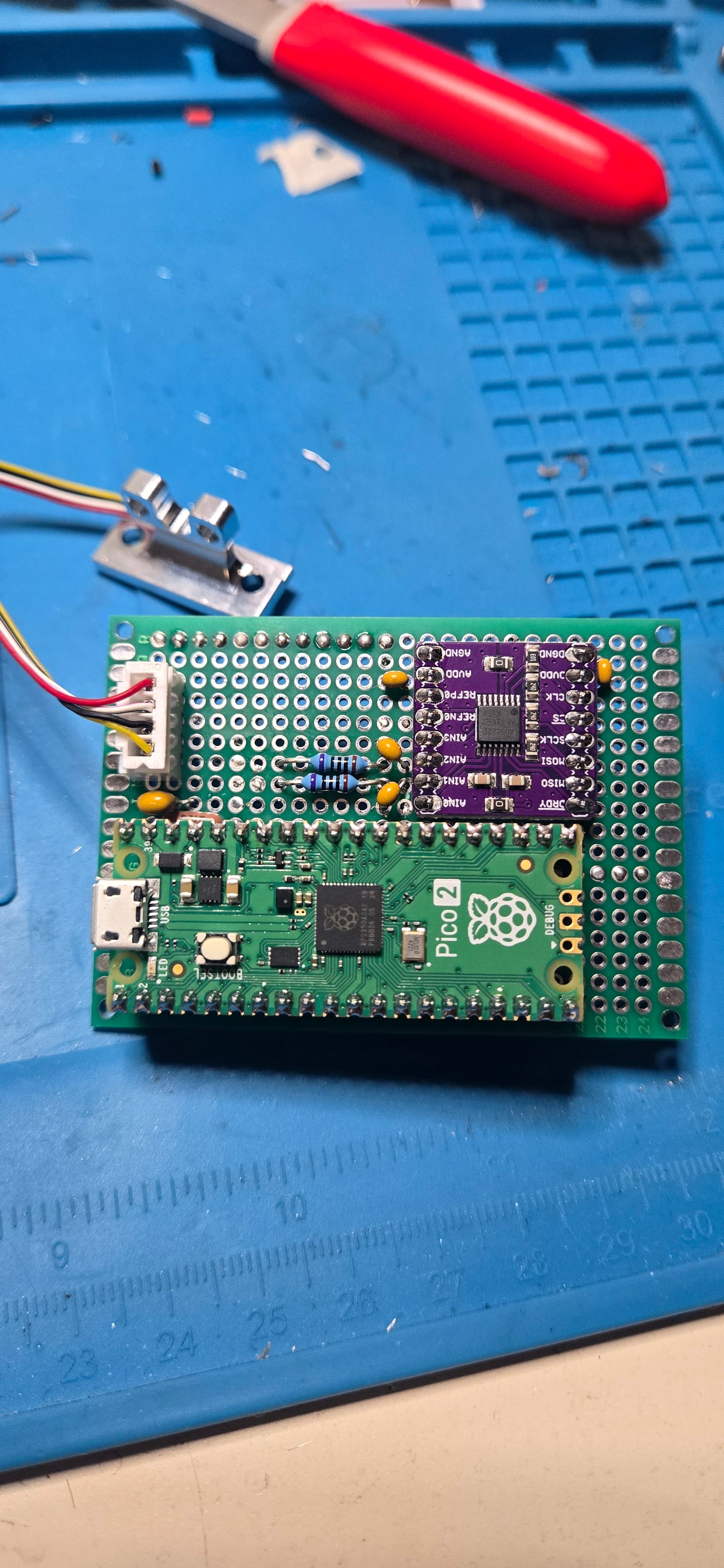
The Mellow3d photos posted above show the 2 channel IC. The part marked 6J7 looks to be a Union UM1560S-47 which was a 4.7V output LDO. I couldn’t find a match for the part marked 431, closest were some 3v3 LDO from Ricoh or Torex but those were 5 pin vs 3. The two stage voltage regulation is desirable to minimize power supply noise but it looks like they have the analog and digital 3v3 power are shared. In my option, a separate low noise power supply designed for analog measurements should be used.
But I still ordered two kits anyways, mainly for the load cell…
When was the last time you saw a popular product for 3D printers not available.
The approach I outlined above has been honed over the past twenty plus years and these companies are very good at understanding customer demand as well as keeping costs low.
First, they have a very good idea of the customer base and its total requirement over several years. What do you think is the total requirement for this product - 5,000 sets? It’s almost always cheaper for them to build the lifetime supply than to worry about having a Just In Time (JIT) production model (this was a situation I had to debate on several products we built at Celestica years ago where the company was firmly entrenched in the idea of JIT for all products).
Secondly, why do you think the supply of components will dry up? There are tens of thousands of electronic products coming out of China every year - much less than half go to North America and Europe:
This means there is very robust activity in procurement which, as I pointed out above, involves trades and spot market purchases. When parts become available, the people involved will look to see what is being used and decide whether or not to take on additional inventory.
Thirdly, the product is wildly successful and the assembled product is sold out in short order. The first course of action is to work the networks and find the required components. If the parts can’t be found, then the PCB is respun with what is available and the resulting product is presented as being “New and Improved”.
Again, the companies and individuals involved in manufacturing in China have been doing this for decades and they’re very good at it.
The last thing you should be worrying about is supply.
The solder tabs on the strain gage are the same foil as the gage grid. It is very, extremely, incredibly thin and delicate. I would never ever solder PVC insulated wire directly to the gage. I was trained to use 34ga enameled wire and glue that wire firmly to the specimen. we had “solder tabs” (basically extra thin fiberglass PC board) we would glue down to make the extension wire connections.
The potting Mellow has used IS NOT a suitable strain relief.
For this unit with the connections already made I’d put a screw* in the threaded hole. Holding the individual wires with tweezers near the white potting form a S bend in the wire and secure the wire to the screw. Zip ties are too big, strip a twist tie from a loaf of bread and use the soft iron wire inside. Once all 4 wires are tied down pot the whole mess with an adhesive of your choice. Avoid unfilled (clear) epoxy as the shrinkage during cure can pull wires off (ask me how I know).
Edit *16 or 20 mm screw bottomed in threads to create a pin to tie to.
Probably off topic but while we are waiting for insight from @garethky what I want to know is how far below nominal Z0 are each of those forces?
If you can read the force in real time babystep down until you see 20g, down further to 50g and finally 250g,
Knowing the velocity that causes the overshoot to the higher forces we can calculate a total reaction time for the system. The bad part is those times include the data read delay, data transmission delay, processing delay and the mechanical delay from motor inertia.
@garethky are the force measurements timestamped by the MCU that sends them to the host? If so can you “look back” to where the motor was then instead if where it is when the the reading is eventually processed. Wouldn’t stop the overshoot but might give you a more consistent result for Z0 if the transmission and processing delays are variable.
That’s a pretty unique thing that this probe does. It takes force readings then then uses linear regression to find the moment in time when the force = 0. It then tells the Klipper homing code where that is (actually when exactly that was). So its resolution isn’t limited by how fast it can stop the axis.
The time stamps are worked out in a very clever way. Kevin developed a linear regression model for time, similar to how the MCUs clocks are synchronized. So each reading has a time assigned to it in the host. This is more accurate than when the reading was taken because we don’t use interrupts to record time on the MCU.
How accurate the system can be is limited by noise and sample frequency. Unfortunately those two things are competing priorities.
Coming back to this point(this isn’t directly meant for you just relevant to the quote), after messing around with using a load cell probe for a few days I’ve kinda decided that MAYBE using something standalone which interacts with klipper as just an endstop pin(what the mellow alps does) may actually be the way to go. For one simple, yet kinda big reason. You get two probes essentially. You can use the load cell standalone as your z endstop for finding Z0, then use a [probe] for meshing. This started to cross my mind after seeing how slow I needed to probe to keep maximum force at a low level. I don’t want to be meshing at .05mm/s The big drawback is I loose all the wonderful work of the load cell probe integration. Thoughts and opinions?
EDIT. Changed my mind per convo on discord. Forget I said anything lol