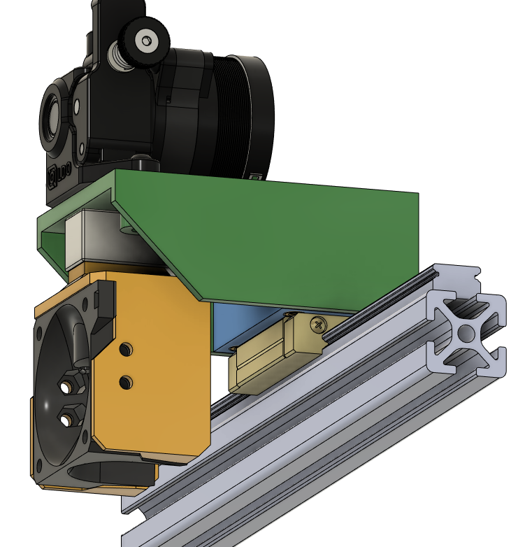
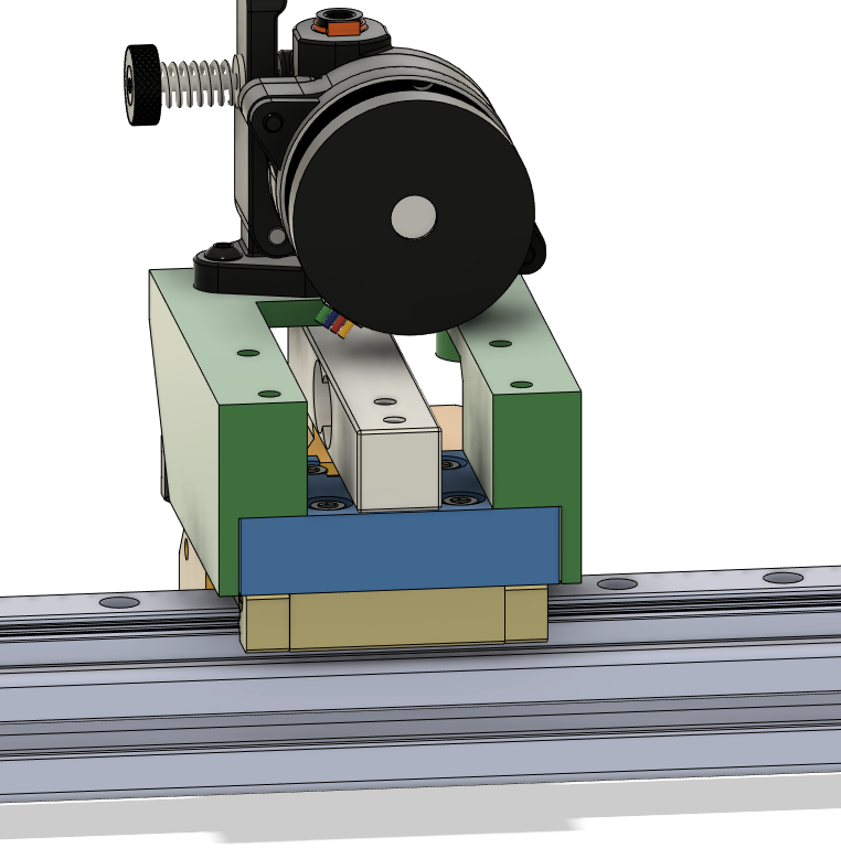
I just started modeling something up in Fusion360, not conforming to any standards, just trying to get something on one of my old printers that uses a linear rail on the X-axis. But I did import an EVA3 hotend adapter and modeled around that, which made that part of the design pretty straightforward.
In the pictures, the extruder is mounted to the green part, the hotend to the yellow part attached to the the strain gauge. This means when the extruder pushes filament into the hotend, it will push the green and yellow/strain parts away from each other. However, this relies on me drilling a 4mm thru-hole in the strain gauge for the PTFE to pass through.
These bar strain gauges are not ideal, but it’s what I had and it’s not terrible either. Have done nothing with it yet. Got a few other priorities, but I already printed parts to give myself some motivation to start playing with it. I have an HX711 amp though it sounds like the sampling rate on that might not be good enough. Open to recommendations.
(I have more pictures but my social rating doesn’t allow me to attach more than one)
It uses the standard approach which modern cnc machines use. It fits a linear function to the force-distance measurements, which can be used to calculate the point of contact. There are some tricks on choosing which data-points to include in the linear regression. Also there is some logic for automatic retrying if no clean measurement is reached, e.g. when there is too much molten filament on the nozzle. The steppers are stopped at a fixed force threshold.
For me it works well, in the future I might add the ability to sample multiple points of the bed, as textured sheets can introduce some inacuraccy.
The bit banging code for the communication with the hx711 had some (now fixed) timing problems, I haven’t tested this on a slow 8-bit mcu though. But it should be fine as well.
In terms of setup anything will work, you just need a hx711 load cell adc for now.
That’s closer than I got and I think basically where we need to go next. I think we need to merge what you are doing on the python side for the collision detection with what I’m doing on the C side to integrate with trsync. Ultimately we would like something that can be merged. See: Comparing Klipper3d:master...garethky:adc-endstop · Klipper3d/klipper · GitHub
I agree. The trsync should be used before merging. If you can help out with this that’d be great. Your trsync implementation looks fairly compatible. Currently the load_cell module just sends up to 3 stepper oids, and uses the manual_stop() to stop the steppers.
Also, we could add the ads1263 adc to the pull request.
Because the load cells adcs have different requirements than the heater adcs, there is a new interface and pin_type. You can see if this also works for the adc1263, or if there should be changes (Right now you would have to send the sample rate at configuration time, as the query command doesnt include this)
Even though its not implemented right now, i wanna keep the option to use the internal adc for load-cell probing in the future. This also drives some of the decision to register the adc with the pins module.
My strategy was to create a new endstop type that triggers based on values from an ADC. The LoadCell reports samples directly to the Enstop but buffers them for reporting back to the MCU (this keeps the traffic down as the sample rate goes up and is what Kevin implemented for the angle sensors). The endstop should be compatible with all of the homing code but I never got reliable enough triggers to fully prove that out.
The rest of the code is just plumbing to get the ADC to work etc. The near term plan is to rip out the EMA filter stuff so it just has a tare value and a trigger threashold. That will make it look even more like your impplementation. I think form there it would be easier to try to merge the two together.
With the super low sample rates and low bit resolution of the on board ADC I wouldn’t worry about supporting it. I’m genuinely worried that people will think this “just works” and they don’t need dedicated hardware.
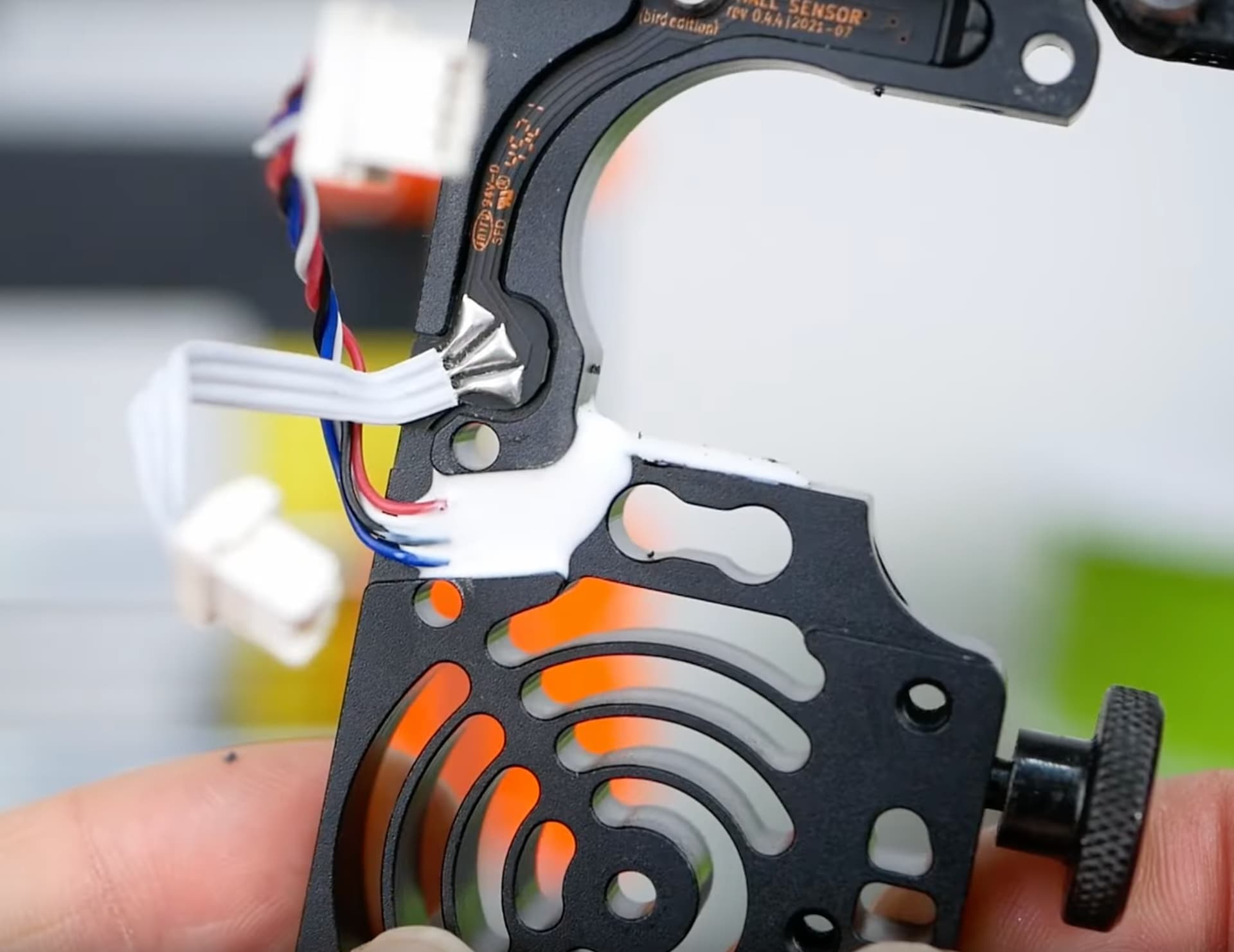
This is the other strain gauge idea that I’ve had. Its based on a flexure membrane which allows motion along the Z axis and twist about the X and Y axes. This allows for probing in the X/Y and Z axes with about the same amount of strain in the membrane for each.
It has some pros:
This one is designed to be cut with a fiber laser out of 3mm thick 6061 Aluminum, which is a very cheap process
If you step up to a Wire EDM process the part can get even smaller in X/Y.
The mount (blue part) that connects it to the extruder can be a 3D printed part that’s easy to integrate into a toolhead.
Potential for a very short distance between the extruder and hot end.
The major cons are:
The 40mm x 40mm footprint in the X/Y plane which is going to interfere with part cooling in a lot of existing toolhead designs.
This is not as well tested as beam load cells.
I suspect that 2 strain gauges will be needed to capture X and Y strain.
I also like Prusas approach to having the strain gauge mouted into a monolithic aluminium block that connects directly between the extruder and hot end for consistency.
The arrangement of having a diaphragm in the printer head is very subject to damage by even relatively small impacts in the XY directions. It can be improved by having a second diaphragm separated by a small distance - say 8 to 10mm.
True, using the onboard adc will require some sort of analog amplifier, and the mcu should be close to the load cell. But it will offer really good latency. With the current implementation i should add a note that external hardware is needed.
The buffering code is nice, does it buffer integer values or raw communication data right now? maybe this should be used for all load cell adcs.
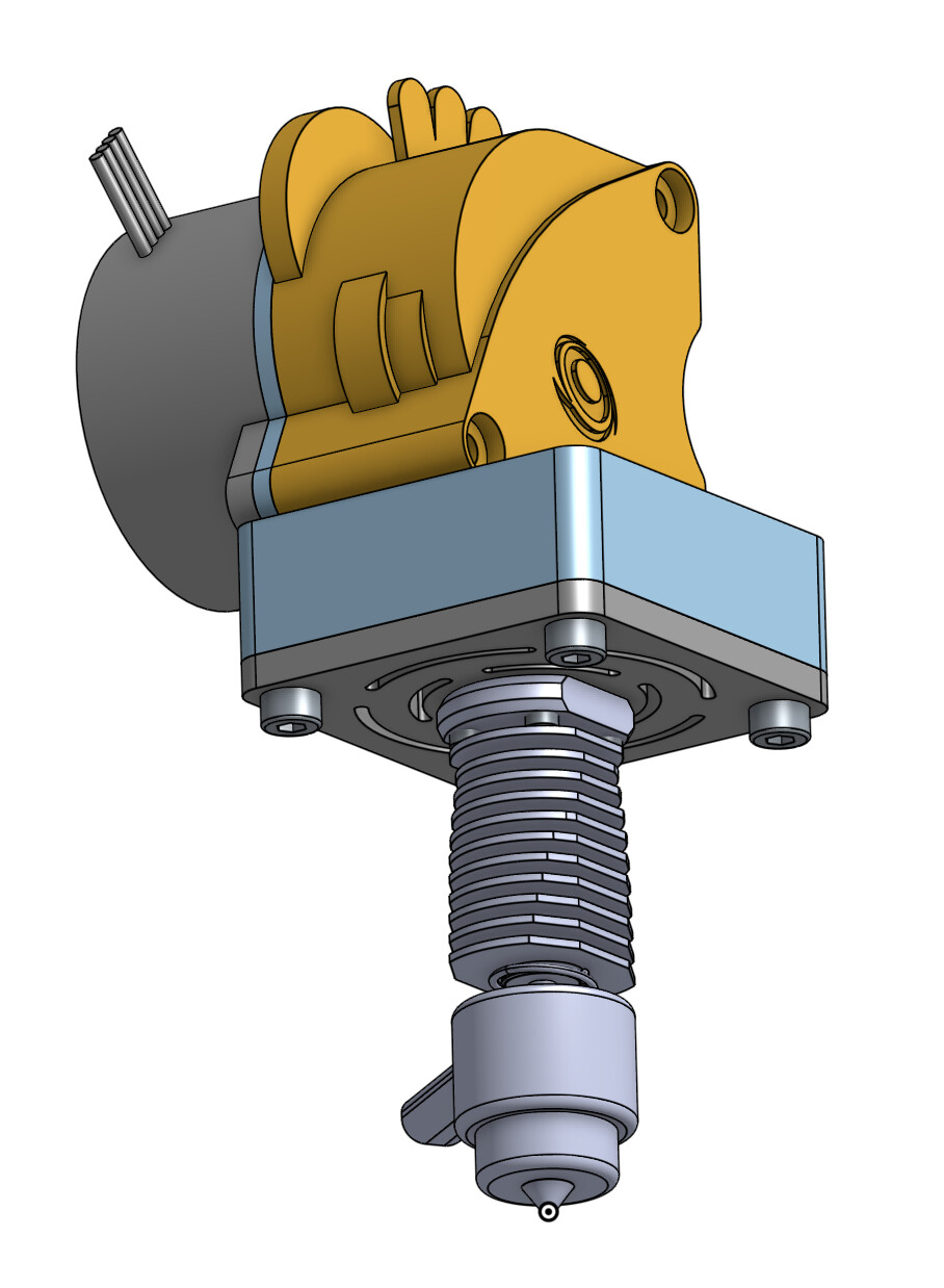
I like how Klipper has built the heat sink and mount for the hot end into the same aluminium frame that the extruder is bolted to. I am going to try and do the same for the SuperLight version of the print head for the Rat Rig V-Core 3. Design will be based around using the Rapido hot end (but not the Rapido head sink) and a Orbiter 2 extruder.
This is the kind of thing I am thinking of.
Manufacturing the aluminium part is relatively easy for me. embedding the strain gauge is something I need to know more about.
2510 heat sink
fan mounts to front four holes and these can carry on through to mount the entire assembly to a front face of an extruder.
Still a couple of bits to work out…I haven’t finalised the mounting to the face plate but for the strain gauge to work, the integrated heatsink/extruder (IHSEM?) mount needs to be mounted to the face plate via the top plate of the assembly. And all mount hardware needs to be easily accessible for servicing.
This design only required changing the face plate and top plate from the Superlight print head for the Rat Rig V-core 3 so it is compatible with all the other options for the Superlight print head.
[Update: However since this version I have completely revised the design which can be seen in posts further down.]
I knew the noise was bad but because the values coming out of the ADC are unit-less I could not quantify how bad it was. I implemented conversion from counts to volts and a process for taring and calibrating the scale with a known weight. Now I can see force, and noise, in grams. Results for noise (max force - min force over 1000 measurements):
BTT Octopus on board 5V supply: ~125g
Dedicated Meanwell 5V supply: ~5g
So that was really bad! +/-2.5g is still pretty terrible vs a scale with a battery, but for our application I think its going to be fine. A power filter would certainly improve things. That’s a big downside of the boards I have seen, no input filtering at all.
I also pulled in numpy and computed the standard deviation, as etotheipi suggested, and 5x that as the “trigger weight”:
I guess, I posted in a deserted discussion on mechanical design. Just want to chip in my two cents. If we want to go for off-the-shelf cheap load cells, those are quite bulky. Hence orienting them for direct measurement will not allow sticking to conventional toolhead packageing.
Hence, here’s an idea: how about using a lever to change the direction of the forces registered by the load cell.
If we go for a levered design, we could amplify/decrease forces mechanically, which could help the sensitivity of the measurements. Besides, a lever allows limiting forces on the load cell as it can be designed as natural breaking point. A Lever would also be most sensitive around cero load and allow to design for a well defined movement with one degree of freedom in z direction.
If you think this may be of interest, I could work on a design. I’m currently on business trip and thus could look into this in a couple of weeks. Regarding xyz measurements, this is probably very tricky to achieve with standard load cells. The other design requirements should be doable.
Shaking the frame of the printer causes more than 3g of disturbance. I’m gonna guess that 50g trigger force is going to work out fine on this setup.
Btw, I mentioned in my original proposal that there there were actually tweaks to the idea to be made.
Instead of Mean and StdDev, Median and Median Absolute Deviation (MAD, which is approximately 0.7*StdDev). This should work very similarly, but immune all outliers in the sampling process – for instance if the machine is bumped during the process those samples will minimally affect both the median and the MAD.
I was saying that 5 stddev would be tweakable because it’s probably unnecessarily conservative. You could likely do 10-15 stddev (well ~15-20xMADs) and it would make it robust against external factors like someone bumping the machine while it’s expecting a collision, while still detecting it soon enough before parts start deflecting. We could of course have an absolute threshold/backup, but that assumes we know the conversion for the unknown load cell. I like that this could be reliable for any load cell without calibration. But I need to experiment a bit to get confidence in that.
If we want to go for off-the-shelf cheap load cells, those are quite bulky. Hence orienting them for direct measurement will not allow sticking to conventional toolhead packageing.
Hence, here’s an idea: how about using a lever to change the direction of the forces registered by the load cell.
I really like this idea, because I think it makes sense to use standard load cells that you can self-source for cheap, but I found it super awkward to integrate this monstrosity into the printhead. I’ve already printed out my awkward design (pictures in my previous post), and I’m just waiting for a clear day on my calendar to pull my printer out of the enclosure and start experimenting.
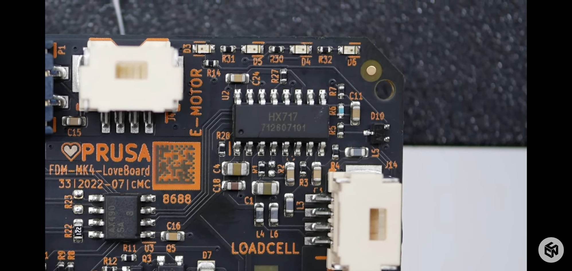
I see Prusa is using a much smaller one, and @MFBS also had a smaller one but I couldn’t tell if they were custom. From a DSP perspective it shouldn’t matter, I just want to pick something that is easy to source.