Strain Gauge/Load Cell based Endstops

Done quite a bit more work playing with different mechanical designs today …but still not happy with anything I have come up with. I don’t want to compromise the tool head design by making it heavier, bulkier or less rigid. I feel Prusa came up with the right idea to integrated the extruder mount, hot end heat sink and load cell. I am trying to come up with a design where the load cell can be a bolt on component for easy replacement and hopefully the ability to use an off the shelf one.

Packaging off the shelf ones is going to be really tricky unless we can find some small ones. Machining parts in aluminium using Chinese prototype companies is actually quite cheap even in low volumes but I would like to avoid having to make the load cell itself. But happy to machine the parts to hold one.

1 Like

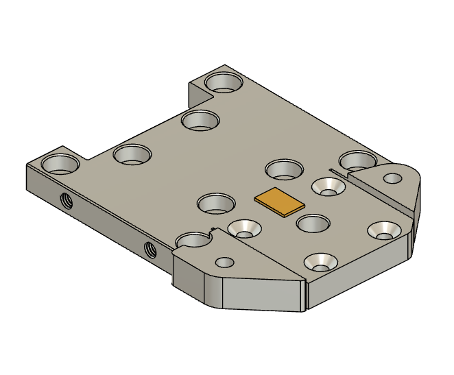
OK getting a bit happier with the design. This design still has a little work to be done, back plate is just a place holder and I need to come up with a mount for the X end stop switch. (I don’t think with this design that th strain gauge can also be used for the X stop end switching as well as the Z probing).

But I feel this idea and the packaging is worth developing further.

It is specifically designed for the the Orbiter 2 and Rapido hot end (and should work with the new prototype Rapido 2 coming out shortly from Phaetus with a very small tweak to the heat sink (larger diameter hole for the larger diameter heat break.)

Current version places the tip of the nozzle at the standard Rat Rig height.

Happy to make all files available in Fusion 360 when I have finished and all final design will be Non Commercial use Open Source license.

Both the top plate and the heat sink are custom aluminium machined parts. If anyone else wants the final design I will be happy to supply these at cost.

The tongue of the top plate that the heat sink is mounted to can ‘flex’ up. [Edit 1/5/23. The top plate can only flex up until it hits the underside of the extruder. The base of the extruder can act as a stop to prevent the tongue being deforemed in the event there is a hard hit on the bed. The amount of flex allowed could be adjusted with shims under the extruder base.]

I have opted to use a glue on strain gauge on the tongue of the face plate.

The VZbot inspired way of attaching the belts allows me to entirely do away with the front face plate.

In my implementation I have run cap screws from the top plate to the bottom plate inside the printed vertical parts. I have also extended the cap screws from the front motor mount down into the printed parts as well. In testing the assembly seems very rigid.

Rather than repost this each time I make a mod to it I will just update here if that is OK?

1 Like

Location of BF350 strain sensor shown in gold

1 Like

I see what you are doing now. I think one of the Ender machine (maybe) has a load cell in it kind of like this?

I 100% agree with this. Getting this done is a real chicken and egg problem. Wait till you see pictures of my chicken! :chicken: :rofl:

Ender’s implementation of their strain gauge has the straing gauge on one substrate that mounts the heat sink and the extruder on a separate substrate.

I really wanted the extruder and heat sink mounted on a single monolithic piece of aluminium (Like Prusa has done) as I think it will give much better repeatability and consistancy.

Yeah I figure I am working on the egg mount and hoping others can come up with the klipper chicken.

1 Like

The anycubic Kobra Plus and Max have one built in. I am actually very interested to see what happens here as that is what I have and this method of bed leveling has proven extremely repeatable and reliable. Their implementation uses a breakout board on the print head doing who knows what. I am in the process of reverse engineering their custom cables, so I’m not sure what type of signal comes out of that breakout. It is possible that it does all the “computation” and triggers a high/low state to the mainboard.

Could you get us a macro photo of that board showing us what chips are on it?

I considered this approach but dropped it. The Klipper way it have configuration for everything driven by 1 command and control system with all of the timing integrated. We would never be able to fully correct for timing on an external board (unless there was a back channel to it). Seemed simpler to just use the sensor chip directly.

The big advantage of a board is integrating with printers as if its a switch. No code required.

Ok, I seem to have gotten stable calibration and probing behaviors so its demo time. @MFBS, here is my chicken :chicken: :poultry_leg:

Even without the linear regression code to pinpoint the triggering time I can get really good results from PROBE_ACCURACY at 1mm/s: (note: this printer has a custom belt reduction + ball screw Z axis, not the stock tool changer one)

PROBE_ACCURACY PROBE_SPEED=1 SAMPLES=10 SAMPLE_RETRACT_DIST=3
PROBE_ACCURACY at X:200.000 Y:125.000 Z:4.623 (samples=10 retract=3.000 speed=1.0 lift_speed=5.0)
probe at 200.000,125.000 is z=1.613229
probe at 200.000,125.000 is z=1.612639
probe at 200.000,125.000 is z=1.614410
probe at 200.000,125.000 is z=1.612049
probe at 200.000,125.000 is z=1.612639
probe at 200.000,125.000 is z=1.614410
probe at 200.000,125.000 is z=1.615000
probe at 200.000,125.000 is z=1.615590
probe at 200.000,125.000 is z=1.615000
probe accuracy results: maximum 1.615590, minimum 1.612049, range 0.003542, average 1.613760, median 1.613819, standard deviation 0.001194

At 5mm/s its, of course, worse:

PROBE_ACCURACY PROBE_SPEED=5 SAMPLES=10 SAMPLE_RETRACT_DIST=10
PROBE_ACCURACY at X:200.000 Y:125.000 Z:11.717 (samples=10 retract=10.000 speed=5.0 lift_speed=5.0)
probe at 200.000,125.000 is z=1.625625
probe at 200.000,125.000 is z=1.619132
probe at 200.000,125.000 is z=1.616181
probe at 200.000,125.000 is z=1.614410
probe at 200.000,125.000 is z=1.610868
probe at 200.000,125.000 is z=1.627986
probe at 200.000,125.000 is z=1.618542
probe at 200.000,125.000 is z=1.622674
probe at 200.000,125.000 is z=1.623854
probe at 200.000,125.000 is z=1.613229
probe accuracy results: maximum 1.627986, minimum 1.610868, range 0.017118, average 1.619250, median 1.618837, standard deviation 0.005383

The triggering force is set at 50g and can be adjusted from the config. It takes some number of ms for the trsync to stop the motors so the peak force seen is 75g when probing @ 1mm/s and 120g when probing at 5mm/s. But this seems very gentle on the printer which was the goal. The config looks like this:

#####################################################################
#   ADS1263
#####################################################################
[ads1263]
spi_bus: spi3
cs_pin: SPI3_CS
gain: 5         # Gain = 32 (max)
sample_rate: 8  # 400 Hz

#####################################################################
#   Load Cell & Load Cell Endstop
#####################################################################
[load_cell]
sensor: ads1263
is_probe: True
z_offset: 0.0
counts_per_gram: 71968
trigger_force_grams: 50.0

Code updated: GitHub - garethky/klipper at adc-endstop
There is still a long way to go to a safe an accurate system:

  • Improvements are needed for calibration, usability and safety.
  • Incorporating the HX711 sensor
  • Incorporating linear regression to find the exact time of contact.
  • Incorporating a high pass filter as seen in Prusa’s implementation

I’m working with @D4SK and @etotheipi on these topics.

One major roadblock in all this has been noise and reliability. I seemed to have solved this by using the 5V regulator on the Octopus board and adding a 330uF filtering capacitor. Using a dedicated PSU reduced the noise but I got weird spikes and sensor reboots (which are now detected and shut down the MCU for safety).

If you are looking at making boards for this application, please pay attention to power filtering! Just throwing a sensor on a PCB is not enough. This capacitor took the noise down from at least 20g to less than 1g. Smaller caps did nothing. Ti has a board design guide in their manual.

4 Likes

That is awesome progress. I have made good progress on my mechanical design for a Rat Rig print head and it should be finished and ready to begin manufacturing a prototype by the end of the week.

Just need to do the part cooling fan mount (I will probably use CPAP kit for my own printer that I have, but will do options for other people for other popular fans).

I have updated my earlier pics (scroll up).

Wish I had your skills with the coding and electronics but hope my ideas for the mechanical design can help inspire other mechanical options.

Some interesting information here on how Prusa are implementing their load cell.

1 Like

One aspect to Prusa’s mechanical implementation is that the strain gauge is also detecting the upwards pull force when the extruder pulls filament from the roll. I think my location on the ‘flexible’ tongue of the hot end/extruder mount will probably see less variation in the strain guage resistance when the extruder pulls filament from the roll.

On the plus side this should mean that the filament pulling force should effect the Z probing less.

On the downside this means it may not be as good at detecting when filament is not feeding freely from the roll.

I think with my mechanical design the ability to read this upward force can be tweaked by changing the length of the slots cut into the top plate to created the ‘tongue’.

You can do interesting things with measuring the extrusion force. My printer (Renkforce RF1000 from 2015 or so) is able to do so even ex factory. A small community around its original (Repetier-based) firmware has implemented several algorithms trying to make use of this. One of these algorithms I have already ported to Klipper:

The idea is that a high extrusion force in the first layer indicates that the distance between nozzle and bed is too small. It will increase the Z offset slowly until the force is normal again. This can be used e.g. to compensate for thermal elongation of the hotend.

The downside I see of this approach: If the extrusion force can be measured with the load cells, the extrusion force will also physically bend the load cells. This will naturally mean the hotend moves slightly closer to the bed. You have to dimension the load cells such that this effect is small enough under realistic conditions. In case of my printer, the original hotend with 3mm filament diameter required quite high forces which sometimes lead to bigger displacements. If you try to print 0.1mm thick layers and your hotend moves down by 0.05mm, you have a problem. At least quality will suffer. I have exchanged the hotend a long time ago with a 1.75mm E3Dv6 which require much less force, so I do not have this issue any more - but of course this depends on the used load cells. I have two TAL220B-typed load cells rated each 5kg. Extrusion forces are for my typically around 3kg now (5-6kg with the old hotend). Maybe this can serve as a rough reference.

1 Like

Prusa mentioned, in the live stream that one feature of their load cell is that the main supporting member is not the load cell flexure. So if there is a toolhead crash it wont cause the flexure to suffer permanent deformation before the rest of the part does. That’s a pretty good advantage of the design. No one wants to replace and expensive part because to a simple mistake.

1 Like

I missed that in the live stream when I first watched it, but I had wondeted at their location of it. Now I understand it.

Thinking out loud.

As you and Prusa point out, Prusa have designed their Extruder/hotend mounting braket so that any permanent deformation (due to severe impact) occurs at a stress riser point that is at a different location from their load cell. In this way they negate the need to recalibrate if there is an impact sufficient enough to cause non plastic deformation of the mounting braket at the sensor mounting point. Smart.

In my playing with designs I did the opposite. I specifically designed a stress riser at the same location as the load cell.

My thinking was that by placing the load cell at an engineeried stress riser point where the most flex would occur, I could achieve the highest sensitivity.

However it might be worthwhile to consider Prusa’s approach and to engineer a sacrificial deformation point that is not conincident with the load cell mounting. The downside to this is, the need to tune the forces required to ‘bend’ the two flex points relative to each other.

The strain sensor flex point must be flexible enough to be able to detect a relativey week deflection force when the nozzle hits the bed.

The sacrificial deformation point must be weaker, but strong enough to not reduce the accuracy of the strain gauge measurements (so that the processing can still determine the difference between a clean nozzle hitting the bed and a nozle with semi molten filament hitting the bed) yet strong enough that it does not pernmanently deform due to ‘normal’ probing forces.

To simplify things I can either take an intuitive gusess at the strength of the flex points or initially ignore the desireablity of a sacrificial defromation point.

I am thinking the second option might be best/simplest, but to consider capacity in the design to accomodate a sacrifiical deformation point at a later date if it proves desireable or necessary in practice.

1 Like

The other thing I noted from Prusas’s explanation is that they considered the bed’s flex would be different at different locatins on the bed. This flex could occur in the bed itself or due to fractional rocking of the bed on it’s carriage or mounting points. (Especially if using something like a three point Maxwell kinematic coupling).

It would be nice to have a database for the fractional flex at each probe point on the bed to reference against the measurements to provide the precision that may be needed.

I am guessing this coujd be in the form of a table within Klipper that could be written into by the user when initially tuning the set up (or copied from another user (who has already established the values) with the same type of printer)

I’m excited to get to the point of working on the linear regression part of this. But before I can do that I still have a LOT of work to do in Python and C (I’m working on this night and weekends and the next couple of weeks there will be about zero time for that).

klipper is not a system for one specific printer. I think we need to be careful about hard coding behavior, especially:

  • The code cant have any “magic numbers”. Everything has to be derived from the ADC sample rate, noise floor, counter per gram, probing speed and so on.
  • Probing test moves need to be user defined. If you need to probe both rigid and springy parts of your printers bed you need to set the coordinates for those probes.
  • Behavior on recognizing a bad probe needs to be user defined. The user could manually clean the nozzle, or automatically brush the nozzle, or try to wipe the nozzle on the bed.
  • Likely the entire tap detection model should be a plugin. That way if the initial version is not working well its easy for many others to have a go at developing a better version without having to deal with the complexities of much of the klipper codebase.

We should study Prusa’s probe analysis model: Prusa-Firmware-Buddy/probe_analysis.hpp at master · prusa3d/Prusa-Firmware-Buddy · GitHub
It may be possible to derive the model parameters for a specific printer with a short training routine. Especially if we can find a a way to reliably simulate taps on molten plastic. I made a quick test with a couple layers of kitchen towel under the probe and the profile in the data is clearly different. The kitchen towel makes a curve while the hard bed surface make a linear strain increase. So it might be as simple as sampling a few points on your bed, maybe 10x each, for the “good” data set and then putting down some paper towels and sampling again for the “bad” data set.

1 Like

“Prusa mentioned, in the live stream that one feature of their load cell is that the main supporting member is not the load cell flexure. So if there is a toolhead crash it wont cause the flexure to suffer permanent deformation before the rest of the part does.”

One other good approach to this issue (suggested in the Rat Rig discord by member ‘elco’) is to have a stop that limits the load cell flexure. In my current mechanical design this is relatively simple for me to implemetnt. The base of the extruder can act as a stop to prevent the tongue being deformed in the event there is a hard hit on the bed. The amount of flex allowed could be adjusted with shims under the extruder base. The amount of flex required to get the required force measurments should be very small and well below the elastic limit of the aluminium top plate…

I think it is time for me to order some strain sensors and a ADC amplifier board and make a prototype tongue plate and do some measurement tests.

I am looking at quarter bridge load cell set up maybe with a second dummy srtrain for temp compensation. In which case I need to mount it somewhere on the top plate at the same temp as the other strain sensor where it will not be stressed…not easy with my current design.

I could use a half bride setup but this would require mounting the second strain sensor on the otehr side of the tongue plate…which is also problematic with my current concept…might have to go back to the drawing board.

For a strain gauges I am looking at a BF350 at this point.

I would like to use an HX717 but haven’t found a suitable ADC amplifier board yet. Can anyone point me to one?

I am on a steep learning curve.

So life has been in the way, and I haven’t had time to hook up the new load-cell printhead to my old printer. But I’ve been thinking!

Someone mentioned that you can detect the correct height based on extrusion force extruding on the first layer. Has anyone thought about that yet? I feel like certain calibrations or tweaks could be made to a lower-quality mesh (perhaps because of the variable-bed response or blobs) based on the primeline, skirt, or even in real-time as you are printing the first layer. I haven’t fully thought it through, just throwing it out there as a potential avenue to overcome some of the issues mentioned so far. I could see doing a primeline starting 1mm above the detected height, and ramp down and look for the elbow in the extrusion curve.

Alternatively, if we did this right before the bed mesh, doing a primeline like this it would also clear any blobs on the nozzle and you could do a retract and turn on the cooling fan to prevent any further blobbing for doing the mesh. You could try extruding before heating to see that filament is being pushed, and after heating to see what extruding into the air looks like.

But yeah, I know that requiring high temp and primeline is not ideal for a simple Z-homing operation. Just food for thought.

I have a couple of very busy weeks coming up and I wont be able to make much progress on this project. So here is an update:

  • HX711 and HX717 support has been implemented. I looked at a log of different implementations but found that none of us had gotten it exactly right. But of course Prusa had to get it right and their implementation is a great resource. Looking into this also led me to notice that Prusa is using the B channel on the ADC to measure hot end temp in the MK4 (at least that’s what the code seems to say). Long discussion in this thread. Basically if we want to get an MK4 toolhead and graft it onto a Voron as a test platform (which seems like the fastest way to solve our :rooster: vs :egg: dilemma) we might have a sticky problem to solve.

  • I set up a project backlog so that you can see what I’m working on and whats left to go.

  • I spent 3 days looking into Grafana and it was a waste of time. For the kind of high frequency data coming from the load cell, it’s display engine seems to be a bad fit. Basically any data arriving faster than 1Hz makes the graphs flash and become unusable. So I’m going to move to ObservableHQ notebooks. Still javascript but much more useful for doing data science than Grafana. Initial testing of the websocket connection works so another day or so of hacking to get pretty graphs again. (task link)

:beers:

3 Likes