What is Klipper's homing sampling rate?

Basic Information:

Printer Model: N/A
MCU / Printerboard: Discussed Below
Host / SBC: N/A
klippy.log: N/A

I was looking at some main controller board schematics and I noticed that for endstops, the basic circuit consists of a 10k pullup with a 0.1μF cap like what you see in the Manta M8P:

I looked at a number of different 32bit controller board schematics and they all have this basic circuit with the only difference being is that some have TVS protection diodes after the 100Ω current limiting resistor. I put in the qualifier “32bit” above as the RAMPs board just has a 10k pull up leading to a 4050 CMOS buffer for input protection.

The reason why I’m asking what Klipper’s homing sampling rate is that the RC time constant of these two values is 1 millisecond which translates to a rise time of 5ms which seems to be fairly high for getting a precise measurement in a moving system.

I did a search in the Klipper documentation but didn’t find anything regarding the homing sampling time.

This shouldn’t be a problem for most people as it would be a non-issue for X/Y homing and the only “modern” Z axis homing approach where I could see this as an issue would be Klicky or using a microswitch on the end of a servo’s output arm.

By looking at a code seems it’s dependent from homing speed.

command: endstop_home oid=%c clock=%u sample_ticks=%u sample_count=%c rest_ticks=%u pin_value=%c

https://www.klipper3d.org/MCU_Commands.html#stepper-commands

rate calculation from homing.py

def _calc_endstop_rate(self, mcu_endstop, movepos, speed):
        startpos = self.toolhead.get_position()
        axes_d = [mp - sp for mp, sp in zip(movepos, startpos)]
        move_d = math.sqrt(sum([d*d for d in axes_d[:3]]))
        move_t = move_d / speed
        max_steps = max([(abs(s.calc_position_from_coord(startpos)
                              - s.calc_position_from_coord(movepos))
                          / s.get_step_dist())
                         for s in mcu_endstop.get_steppers()])
        if max_steps <= 0.:
            return .001
        return move_t / max_steps
1 Like

Thanx. I’m guessing that this code encompasses homing on all the printer’s axes - for a Cartesian printer, you’ll only get movement in one axis, for a CoreXY you’ll get two for X/Y and for a Delta you’ll get all three. Does that sound right?

Now, it looks like the sample rate is proportionate to speed. The higher the speed, the smaller the “move_t” value is which is used to generate the rate in the sample period (in seconds).

I think this makes sense as I observed that I got better results when I first started using Klipper and I slowed down the movement of the toolhead during Z axis homing (on a Sapphire Plus with a microswitch for the Z axis homing). If there was an error caused by the RC circuit in the endstop pin circuitry, it would be less if the toolhead was moving more slowly, which means a longer interval between samples which would make the RC time constant less significant.

Does this make sense?

As I remember usually each end-stop is controlling dedicated stepper and halting it when it meet’s end-stop criteria, most probably each end-stop+stepper can have unique rate because they can have different configuration.
There is a differences for each kinematic type how homing is done, for example for Delta all 3 axis are done in same time, for Cartesian - one by one.

I’m not sure which values did you use for RC calculation, but if I calculate 1K and 0.1uF - i’m getting 0.1ms, or 100us.

From logic point of view - yes

But if I just imagine following conditions:
Rotation_distance=40
Homin speed=5mm/s
Second_homing speed = 2.5mm/s
Stepper = 200 steps/rev
microstepping = 32

(200*32/40)*5=800
So I’m getting a 1/800=1.25ms for 5mm/s and 1/400=2.5ms for second homing speed and 0.006mm resolution for single step.

If we increase microsteping to 128 - i would get 1/3200=0.3us for 5mm/s speed, but in same time we would get 40/(200*128)=0.0015mm resolution of a single step.

So math is showing that if you have coarse resolution - time is enough to correctly catch that event,
if you have very fine resolution - yes you could experience a RC delay, but I doubt that any existing probe in 3D printing have that kind of precision.

It’s a 10k resistor with a 0.1μF capacitor - the time constant is 1ms. The rise time is 5ms. The 1k resistor in the image I posted is for energy dissipation.

Going back to your example, I would think that most people have their microstepping at 16, which would mean that your numbers double AND with a rise time of 5ms you could get an error of one or two microsteps.

In actuality, I think we’re talking a 10 to 20 micron error.

There is a constant rate used in the homing.py

ENDSTOP_SAMPLE_TIME = .000015

Klipper (from what I could tell when I was messing with it anyways) also keeps account of the step position vs the end stop trigger position while homing and adjusts accordingly.

For example, if the end stop triggered at a step position of X but the actual halt position of the motor is Y it adjusts itself back to X. This assumes that all steppers are synchonized.

Which is the issue I had when I converted all my Z axis drives to CAN bus because then there is a slight propagation delay in communication.

In other words if the endstop is connected to MCU “Y” (in my case the toolhead) it’s trigger signal might reach MCU’s W,X,Y,Z (my 4 Z axis boards) at a very slightly different time. THANKFULLY each board keeps track of it’s stepper pulses by time and the clocks are synchonized so instead of the default “adjust every stepper back by the same amount in the code”, I went back and said “Where were you at X time (the trigger time), move to that point” PER stepper.

To your point though, yes the RC time constant will delay the trigger very slightly. But all the steppers will adjust their positions to that triggered position. So it’s really just the physical distance covered in the time until the logic high threshold value (or low).

I’m going off memory from all that for something I did a few months ago, so I might be mistaken on some of the finer details.

1 Like

Ok, seems we both was wrong :slight_smile:
If you have correct end-stop - Trigger time will be like 100-300ns (0.03us)
If you have “Maker Bot” design - it can give you up to 2ms delay (depend what is connected and what is monitored)

YES same end-stop can have 5000 time differences of trigger signal !
I was not expecting that :slight_smile:

Also we misread the schema logic.
Everything depends from end-stop implementation, it can be Active/Passive/MakerBot more about that here.

We should read your schema following way:
There are pull-up 10k resistor which is required to bring signal to High 3.3v level, capacitor is there just for voltage stabilization, that 1k - yes it’s current limiting resistor.
When end-stop is triggering - it’s shorting signal line to ground to bring signal level to Low state and in this case you have very small resistance, aprox 0.1 Ohm - and this will discharge that capacitor very quickly.
But when end-stop is released - then it take aprox 2ms to charge that capacitor.

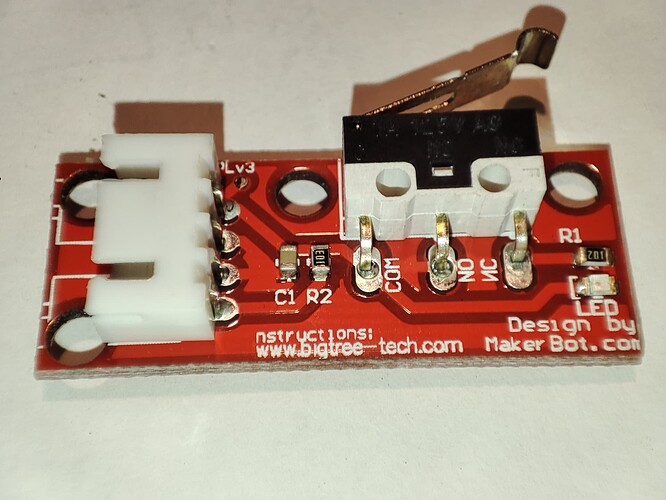
I quickly build that schema and connected MakerBot design end-stop from BTT.
Then hook-up oscilloscope there, here is my findings:

MakerBot end-stop, +5v connected, triggered, 1.92ms to reach 0.8v level

MakerBot end-stop, +5v connected, released, 124us to reach 2.0v level

MakerBot end-stop, +5v disconnected, triggered, 365ns to reach 0.8v level

MakerBot end-stop, +5v disconnected, released, 1.7ms to reach 2.0v level

1 Like

As I said at the start, I was thinking of a simple switch. The Maker Bot endstop adds additional capacitance to the circuit.

Regardless, the critical situation is when the switch closes and that will be very fast whether there is a capacitor on the line or not. When the switch opens you will get a much more pronounced RC curve but that shouldn’t be an issue.

Thanx for taking the time.

Is my understanding correct:

Makerbot endstop-design:

  • Typically 10k / 100 nF
  • NC design, so the important factor is the discharge time of the cap

According to this data:

  • Time Constant is 1 ms
  • Following V_C = V_{C0} \times e^{(\frac{-t}{τ})} the discharge time from 5V to 0.8V would be 1.83 ms (which seems to fit quite nicely to @gaolst measurement 1.92 ms)

The difference to the 365ns is indeed massive.

Yes, it’s correct.

But it should be noted that when End-stop is used for some alignments of the system like in Delta or it’s used as a distance probe - they should be very careful what kind of end-stop they use and what kind of schema they have on board and in end-stop, especially it’s important when user is doing upgrades of mainboard and keeping old end-stops.

If they are not careful - they can get a condition when electronics will create that 2ms delay and if they have very fine microsteping and high speeds - steppers can overshoot by 6-50 microsteps, overshoot depends from speed and rotation distance.

So thumb-up rule rule is following: If your board have capacitance in end-stop chains - You should use passive end-stop which triggers by shorting Signal line to Ground, you can also use Active end-stop which don’t have any capacitance and have same logic - triggering will short Signal to Ground.
Releasing of a triigger should not be used at all.

The “newer” Makerbot style switch is SPDT which avoids this whole issue.

It pulls straight to VCC or GND so there is no charging through the capacitor.
You and Myke are correct that it’s an issue with a SPST switch to ground.

Circuit analysis is below for both if you want to play around:

Makerbot v1.2 Style Switch

SPST Style to Ground

Both have the scope set to 1ms/DIV

Well I actually did use SPDT type of a switch for a test and get those results,
here are photos of it, I’m wrong ?


When high it SHOULD have a direct connection to VCC and thus the current path shouldn’t be through a capacitor. (VCC → Current Limiting Resistor → MCU Pin → Internal MCU path to Ground)

With just a simple switch pulling to ground, when it’s open the “high” is tied through a resistor with the capacitor in the ground circuit causing the RC time constant.

I’ll admit, I second guessed myself about 5x while looking at this and doing the circuit simulation though.

@mykepredko - Any input on this and the two simulations I posted? Maybe I’m the one doing it wrong.

I’ve second guessed myself more than 5x on it.

The reason for me asking it in the first place is that I don’t like to see a capacitor on any line that goes into an MCU (with the exception of negative active reset and power inputs). It started when I was looking at the BTT Smart Filament Sensor V2.0 and in the user manual, it notes that if you’re going to connect it to an SKR Mini V3 E3 you’re going to have to enable the MCU pull up because there isn’t one built into one of the pins that they suggest connecting to (PC12):

When I looked at the SKR Mini V3 E3’s schematic for the IO Pins:

The “PWR-DET” pin is wired the way I would expect but all the endstop pins have 0.1μF caps on them - which lead to the question.

Now, in terms of your simulation - I don’t think you have them right. In neither case do you have a common ground and you’ve added a second power source which isn’t part of either circuit.

For the simple “SPST Sytle to Ground” it should be (and you’ll see the RC Time constant rise when the switch is opened):

Now, as for the “Makerbot v1.2 Style Switch”, it should be (also with waveforms):

I was confused by your original model of the Makerbot V1.2 because it didn’t make sense that the NO contact of the switch was tied to 5V - by doing that, the filtering RC circuit is effectively bypassed and does SFA as you can see by the crisp edges in the diagram above.

I would have thought the correct approach for Makerbot would be to leave the NO contact disconnected so the filtering components are active in the circuit like:

But, when I do some research, I find that is the case, the NO contact is tied to Vcc as per:

https://reprap.org/wiki/Mechanical_Endstop

With the schematic:

Which looks like the “Original design” is probably more correct than the latest one.

From all this, I have come to three conclusions:

  1. The 0.1μF cap was put in by somebody onto a main controller board for some unknown reason and people have copied it blindly without questioning it’s presence.
  2. The 0.1μF cap doesn’t perform any useful function and could be problematic depending on how mechanical endstops are wired.
  3. This thread is probably the deepest discussion on the design of endstops, one of the most critical components in a 3D printer, that has been done in the past 20 years.

I agree with that, when looking into it more than once I was like… What? Why?

And you’re right on the common ground, I did it both ways but they should have been connected to a common ground. I didn’t see it ultimately made much difference in terms of what we were looking at but I redid it so many times I’ve lost track now.

I came to the same conclusion on the capacitor though, In the “newest” Makerbot version it serves no purpose as far as I can tell.

I think someone just took the idea of a bypass capacitor too far and everyone ran with it.

The way it’s wired, it’s not a “bypass” capacitor, it is a “filter” capacitor. You can see the filtering in the simulation waveforms.

Bypass capacitors provide a low impedance path for high frequency noise and do not have a resistive current source in series (like a low pass filter circuit, like the one we’re talking about here, does).

Sorry for being pedantic but it could be the person who put the capacitor in originally, didn’t understand how the circuit would work.

I modeled it this way. IMO the cap does just nothing.

In a regular circuit, it would serve to debounce the switch and reduce the impact of noise. In my first printer 10 years back, this was really a topic and the initial RAMPS boards had not RC circuit on board.
Today, I’d rather consider them detrimental, as @mykepredko pointed out.

That’s the lowest ESR capacitor I’ve ever seen in my life.
(Totally jk I know the simulation won’t work without it.)

To one of Myke’s original points, Even if there was a 5-20 microstep delay. It really doesn’t matter for X/Y homing anyways. Absolute worst that would happen is the first time you home your gantry rams into the side and you’d adjust your endstop to compensate.

For the Z axis everyone uses a probe of some sort anyways, and those that possibly do use a Microswitch have adjusted their Z offset to compensate.

It’s an interesting discussion on how things propagate because no one questions them, and there potentially COULD be a “better design”. But at the end of the day, does it really matter/is it worth it?

1 Like

I did some history digging …
First design of end-stops was to use mechanical switch in default LOW state and when triggering is happening - it would go to HIGH level,
that capacitor was introduced for pure mechanical switches as a countermeasure to solve switch “bouncing” and EMI protection (
more about that here)

Then MakerBot did develop optical end-stop which was working other way (trigger when on LOW) and it was used in their boards which didn’t contain that capacitor, eventually they create mechanical version based from optical version to reduce cost and wiring (SPDT type - 1.0v), in this moment they introduce that capacitor to mechanical end-stop board, so it would be compatible with their mainboards together with optical end-stops which don’t have it.

So MakerBot was handling it correctly - their boards did have only MCU Pin input, pull-up resistors and capacitor (for mechanical version) was present in end-stop itself.

But as time did go forward, different end-stop designs propagated everywhere most of the boards designs did try to follow MakerBot design (trigger on LOW) and eventually moved pull-up and capacitor into their boards.

Now we have them on-board almost in each board designs and if you try to use Optical end-stop - you will get 2 pull-up resistors, if you use mechanical MakerBot end-stop - you will get 2 pull-up resistors and 2 capacitors in same circuit :rofl:

Most probably you are right, but don’t judge just for simple kinematics like Cartesian, for example Delta kinematics is very dependent from exact end-stop triggering, overshoot distance depend from rotation distance and in some hardware configurations your error can reach 0.1mm - which is pretty high for Delta kinematics.

This is true, but I imagine with delta kinematics you’re using the same endstop type on each of the three pillars so it SHOULD (very ideally) even itself out. In other words, They’d all have roughly the same delay within part tolerance that is.

Or, like you said, you can just use an optical or hall effect endstop.

I’ll leave that one up to the Delta printer owners to handle.