Basic Information:
Printer Model: CR10S
MCU / Printerboard:
Host / SBC Raspberry Pi 4
klippy.log
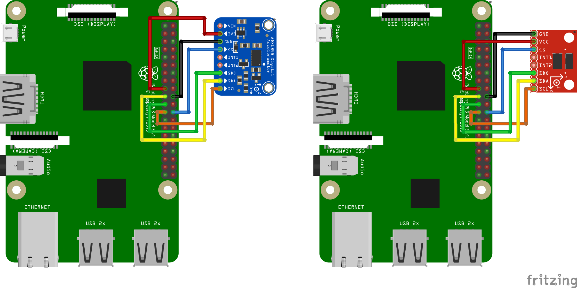
Hello! I was in the middle of calibrating my printer with a brand new ADXL345 Accelerometer, when as I went to move the chip to mount onto my Y Axis, I got burned by some component on the chip in the region of the GND pin. I could tell that it got hot only when there was power to it, and I know that my connecting wires aren’t the problem. It was functioning normally before, and it had only been on for about 10 minutes. I now get an error message when I send the ACCELEROMETER_QUERY command to it. I’m pretty sure that I blew it out, but I am wondering if I wired it to my Pi wrong. I followed this image that’s for wiring it up to a 3B assuming that it would be the same for my Pi 4: https://obico.io/assets/images/adxl345-fritzing-9c07c93be5d414d8a87e5b55ac8986ce.png
But now that I blew the chip, I think that it’s not the same. Does anyone have a wiring diagram for wiring an ADXL345 Accelerometer to a Raspberry Pi 4, or any advice regarding this issue?
By the way, here are the mounts I designed: