BTT TMC5160 PLUS tuning parameters

Basic Information:

Printer Model: custom I3 - IDEX wwith nema23 motors on X1, X2, Z1, Z2 and Y
MCU / Printerboard: BTT Octopus Pro + 2x EB42
Host / SBC: Desktop PC

Hi, I just replaced the old TB6600 stepper drivers of my printer with the ones from the title.
The issue is the following: the Z axis motors, with stealthchop disabled, sound like normal noisy stepper motors. If I enable stealthchop, instead, the motors vibrate and sound like they are shaking the whole machine apart.

-Z, SC ON: Imgur: The magic of the Internet
-Z, SC OFF: Imgur: The magic of the Internet

The X axis motors are very silent during printing, but they ā€œsquealā€ quite badly when i jog them from the klipperscreen ā€œmoveā€ menu, especially the left one (it’s a 76mm motor like the Z ones, so that might be the reason).
The noise on the X axis seems to get better the more it moves, as if there is some kind of autotuning going on.
edit: keep in mind that the X noise is amplified by the aluminium plates holding the EBB CAN boards.

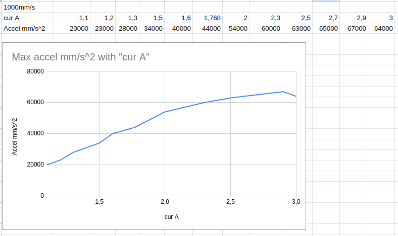
I tried both 36V and 24V, different microstepping levels, interpolation on-off, different currents, but nothing seems to fix the issue, so i guess I should start messing with the tuning parameters of the drivers.
Do you have a clue of which of the parameters listed in the reference for TMC5160 drivers could help to fix this issue?
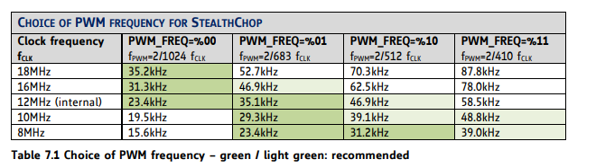
I tried taking a look at the spreadsheet provided by the manufacturer, that should guide the choice of parameters, but changing driver_TBL, driver_TOFF, driver_HEND and driver_HSTRT with the suggested values didn’t bring much improvement if at all.

Did anyone face the same issue and find a solution?

ps: I can’t povide a config at the moment as I don’t have the machine at home, but I will upload it later if necessary.

Thank you :slight_smile:

TBL and stuff do not directly influence noise, they influence, but not like ā€œif you set them correctly, they will be silentā€, IMHO, without an oscillograph this is complicated.

You can play around with micro stepping, which has a larger value and is generally more silent.

About StealthChop, It is useful for up to ~5 RPS. After that, it will not work, and yes it has autotuning.

My 2 cents, it is generally recommended to run a motor at its rated current, the same as the driver. You have now High current drivers. So around 50% of their rated current should be fine.

Thank you for the reply.
The Z axis has a 5mm ball screws, and is limited at 30mm/s. So 6RPS. However the noise is honestly pretty absurd, and is present even when I just babytep the axis 0.1mm, the steps sound like hammer hits :rofl:

If it just stopped working at 6RPS it would be fine, but these vibrations are crazy, and are present at lower speeds too.

For micro stepping I tried up to 128, with or without interpolation, and I didn’t see an improvement.

I thought at the current too, but I have a problem: the motors are rated 2.8 - 3A, so I’m stuck at those values.
Moreover, with the current set to 3A, the spreadsheet suggests that I’d need a CS value of 5 with the 0.022 sensing resistor of those drivers, but also states that values below 16 are bad for micro stepping.
I have no idea of the CS value chosen by klipper.

cfg.zip (6.3 KB)

this is my setup, in case you want to check it out :slight_smile:

Should be 31 CS in Klipper by default, if you set the sense resistor value correctly in the config.
DUMP_TMC will help you to see current registers.
Because 5160 scale current by Global Scaler, not by CS.
CS is used for IHOLD & CoolStep, i.e. for runtime regulation.

if your motors are rated to 3 times less current than the driver, it helps to replace the sense resistor on driver.

Otherwise, there is nothing you can do about it, inappropriate driver, inappropriate motor. Generally speaking low inductance motor are less noisy.

Stealth should work, because it moves frequency to unaudible spectrum.
image
You can try increase PWM_FREQ.

*same about SpreadCycle, there are also frequencies to play.
IIRC, increasing of TBL - will decreasing frequency, and vise versa.
You can find approximate frequency it in TMC5160 spreadsheet, where you are tried to find optimal parameters.

Thanks for the grat tips.
Do you think that replacing the resistors could actually help here?
I know I’m a bit on the edge, but I really didn’t feel like push 3A through regular stepsticks…

I’ll definetly try messing with PWM_FREQ

It is a little too much for them, but as you said motors are rated for 2.8-3А, if there are numbers from the datasheet, you can safely use 2.8A * 0.707 = 1.98A RMS.
Stepsticks are rated for 3A RMS, so they should be able to run them.

Otherwise, if 2.8-3A is RMS for your motors, you can try to increase the current temporarily - and see if sound changes.
(your motors are large)

On external high-current drivers, there are pretty large resistors, so you still can replace them.

But bear in mind this is all about ā€œcorrectnessā€ like they will better sense what happens, and not about silence.
At least I got one feedback, that after replacing the sense resistor - nothing changed in relation to noise.


My 2 cents, I have LDO2504 (rated 2.5A, so I use 1.768), and StepSticks 5160 48V
I’m able to overdrive motors (I only tested that to see a correlation between Ampers and Torque).


Oh, according to your config you are already use only 2A, so 5160 Plus is clear overkill here.


UPD: I got one feedback that overdrive helps with noise.
so, it depends.

Honestly I really don’t have much info on the motors. They were sold as 3A motors (the 76mm of the Z axis) and 2.8A (the 56mm one of the x axis).
i don’t have any way to know if that value is peak or RMS.
For the Z ones the original listing doesn’t exist anymore, but it was probably something like this (same torque rating, same current rating, same dimensions, same 3 motors kit).
I could try to overdrive them for a few minutes to see how they react.
On the config the current values are a bit all over the place because I was testing whether reducing/increasing the current limit made any difference.
However I never experienced skipped steps, so I could have probably made it work with normal stepsticks + active cooling and a lower current value (2-2.5A).
The most current - hungry is the Y axis motor, I have a tmc5160 driver for that too, but at the moment is unused. Having a 10mm ballscrew means I need a very fast motor, and at the moment I’m using a JMC IHSV57 servo for that. But the plan was to install some kind of reduction and fit a stepper motor on Y as well.

That said mine isn’t really a noise issue. The spreadcycle sound is actually quite decent, but having spent money on those drivers I wanted to try the smooth operation of StealthChop.
But the vibrations of the Z axis motors make me belive that there is something WAY off somewhere. It’s not like they are a bit noisy, StealthChop is actually unusable as it would probably destroy the ballscrews pretty fast.
At the moment I’m just running all the motors on spreadcycle and the just sound marginally better than the old TB6600.

I guess I could try to replace the sensing resistor on one driver and see how it works… Would some regular 1/4W resistor be enough? I should be able to solder a couple of through hole resistors in place of the SMD ones.

edit:nevermind, there is a page for that in the spreadsheet, and 1/4 seems a bit low

1 Like
  1. The choice of the drivers will massively degrade their ability to properly control the current: Your drivers are set for a peak current of ~15 A and your drivers are using something around 3 A
  2. The values in the stepper’s data sheet are typically max current ratings, so you want to use Current_{RMS} = \frac{Current_{max}}{\sqrt{2}}
  3. Unlikely that tuning any driver registers will yield any appreciable results
  4. You can replace the sense resistor, but surely not with a regular resistor. This is a very sensitive area of the driver with high requirements regarding noise etc. Something around 0.5 W should do the trick

Edit: Fix typo

Got it. I have a tmc 2209 stepstick laying around, at this point I think the best thing would be to try it on one of the Z stepper motors to see if a reasonably sized driver would fix the issue, before starting to buy and solder resistors.

Would replacing the resistors bring the drivers back to spec for these motors or do you think that there might be other components / design choices that could make the driver not suitable?

Changing the R-sense is enough. Did this already for my drivers.

Note that you will likely need active cooling if you max them out.

:+1: :+1:
Great. I’ll test that and let you know if it fixes the problem.

I noticed a couple of other signs that the drivers aren’t workign correctly.
The motors get way hotter than before (the X axis one is almost too hot to touch, even at 1.5A), and I got a random Z axis layer shift during a test print.

Tell me if I’m wrong:
looking at this schematic I see that I need a 0.1% tolerance resistor.
The step file shows the size of the package (2512)
The 5160 chip datasheet states that that for a 3.3 peak current motor I should use a 0.1ohm film resistor.

The problem is: where do I find a 0,1% resistor in that specific package size? XD

How about this:

Now, I’m not sure of your thinking regarding heat.

If your Nema-23 motor is running at 24V with 1.5A running through it is dissipating about the same amount of heat as a 40W incandescent light bulb. If you’re running at 36V, then it’s dissipating as much heat as a 60W light bulb.

It’s gonna get hot.

How are you verifying the 0.1Ī© resistors on the stepper driver modules are incorrect or that they need to be replaced?

It could simply be that you’re drawing a lot of current through them and they’re heating up naturally, at which point the driving MOSFETs become less efficient and their internal resistances grow, which results in more heat and power being dissipated there and not going to the motors.

As @Sineos suggested, you need to provide active cooling which needs to be defined as it will be more than a little blue machined heatsink with a fan blowing across it.

Check Digikey or Mouser. This type is called ā€œcurrent sense resistorā€.
TBH, I’m not so sure if BTT really lives up to this 0.1% promise, as you hardly get any with this rating (Mouser is like 2 from a total of 40000 resistors in their list).
I settled for 0.5% if I remember well.

Blockquote
How are you verifying the 0.1Ī© resistors on the stepper driver modules are incorrect or that they need to be replaced?

Just to be clear: this resistor replacement stuff i’m speaking about is for the tmc5160t plus, not for 2209 i’m going to try just as a test.
But basically
a) the answers from the 2 guys above (i really don’t know much about this stuff)
b) the fact that the datasheet of the drivers IC is quite specific about the need of using a resistor with a value suitable for the current you need, there is also a table at page 74 with the suggeste values.
c) the drivers are rated for 10 amps (15 peak), and the manual states that active cooling is needed only above 3A (keep in mind that we are speaking about external drivers, not the tiny stepstick with microscopic heatsinks.

Blockquote Check Digikey or Mouser. This type is called ā€œcurrent sense resistorā€.
TBH, I’m not so sure if BTT really lives up to this 0.1% promise, as you hardly get any with this rating (Mouser is like 2 from a total of 40000 resistors in their list).
I settled for 0.5% if I remember well.

That makes things easier I think, on Mouser 0.1% resistors cost as much as the drivers… I’ll keep searching

The link provided by mykepredko could be a good option, I’ll have to check if they ship to italy. Still quite expensive though.

edit: this seems fine and reasonably priced

First; stop taking individual pieces and treating it like the entire system.

The terminal pins used for the stepper motor drivers are probably good for 2A, maybe three. Next, I have no idea of the thickness of the Vin plane or traces used in the PCB (and I doubt you can get that information) which affects the amount of current it can take. You’re probably limited to 2A on the pcb to pin if thermal reliefs are on any of the pin vias (which is very likely if the pin is connected directly to a power plane). How much current is the wiring rated for? How much current is the motor rated for (I think as a rule, NEMA 23s are rated at 3A)?

You may have a rated driver current of 10A but that is meaningless in regards to the entire system.

How does the manual (and a link to it would be appreciated) suggest implementing ā€œactive coolingā€. To me, in an application like this, that means some kind of liquid cooling.

Can I suggest that you go back to the beginning where you installed the '5160 drivers and let us help you work thorugh the problems on the various axes and get things back under control?