OK, I’m hunting down a strange issue on my Voron with the Extruder:
The Extruder Driver randomly errors out with “TMC ‘extruder’ reports error: DRV_STATUS: 20000000 cs_actual=0(Reset?) ola=1(OpenLoad_A!)”
The error does only occour with the round Nema14 motors (the classical Voron Steathburner Motors). I have several Toolhead with Nema14 motors which all produces the same errors. I have ALSO toolheads where I modified a Pancake NEMA17 onto them and driving them around (I’ve had them laying around). The error has never accoured in well over 500h of printing.
Searching around for the error above seems to indicate that the driver is reporting zero current / a broken wire.
So I checked every cable and measured the motor-windings.
NEMA 14 has 2.6Ω an about 500uH per Phase, Pancake NEAM 17 has about 5Ω and about 1.5mH
all NEMA 14 are measuring about the same values, but to me the values all seem pretty low…
My first question would be if anyone ever noticed something like this? Are the NEMA 14 motors I have faulty?
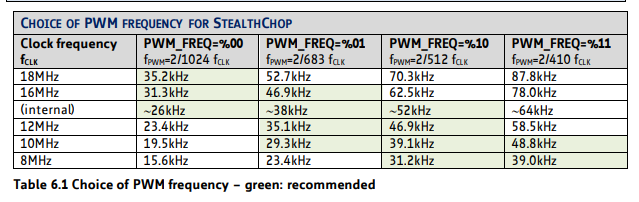
I searche dthe datasheet and found nothing specific about the ninimal required motor inductance. There are two Parameters called PWM_FREQ and TOFF (in the TMC2130 Datasheet) which are controlling the chopper frequency. My try right now is seeting the chopper frequency higher (test running) because i suppose thats what might cancel out the lower inductances (but I’m not very sure, but I did run out of ideas)
I changed the TMC Drivers, changed the toolhead boards, recrimped wires. nothing helps.
The only thing which reliably helps is changing the motor from NEMA 14 to Pancake NEMA 17.
oh and of course, if I switch to a “dumb” DRV8825 Driver everything works perfectly fine.
I think the last checked/changed variable did the Trick:
Changed the Extruder-Motor to a NEMA 14 from Stepperonline (similar resistance and inductance as the NEMA 17 pankake stepper) and it works…
You have a pretty rare setup, so it is hard to guess.
According to StealthburnerFullUSBPD, there would be 20v? I guess.
TOFF is SpreadCycle specific.
PWM_FREQ is StealthChop specific.
PWM_FREQ, even if I understood this parameter,
I do not know why it exists or why anyone would want to mess with it.
The real question, I guess, is why driver reset itself?
Yes, that would be 20V operation on the hotend, that is correct!
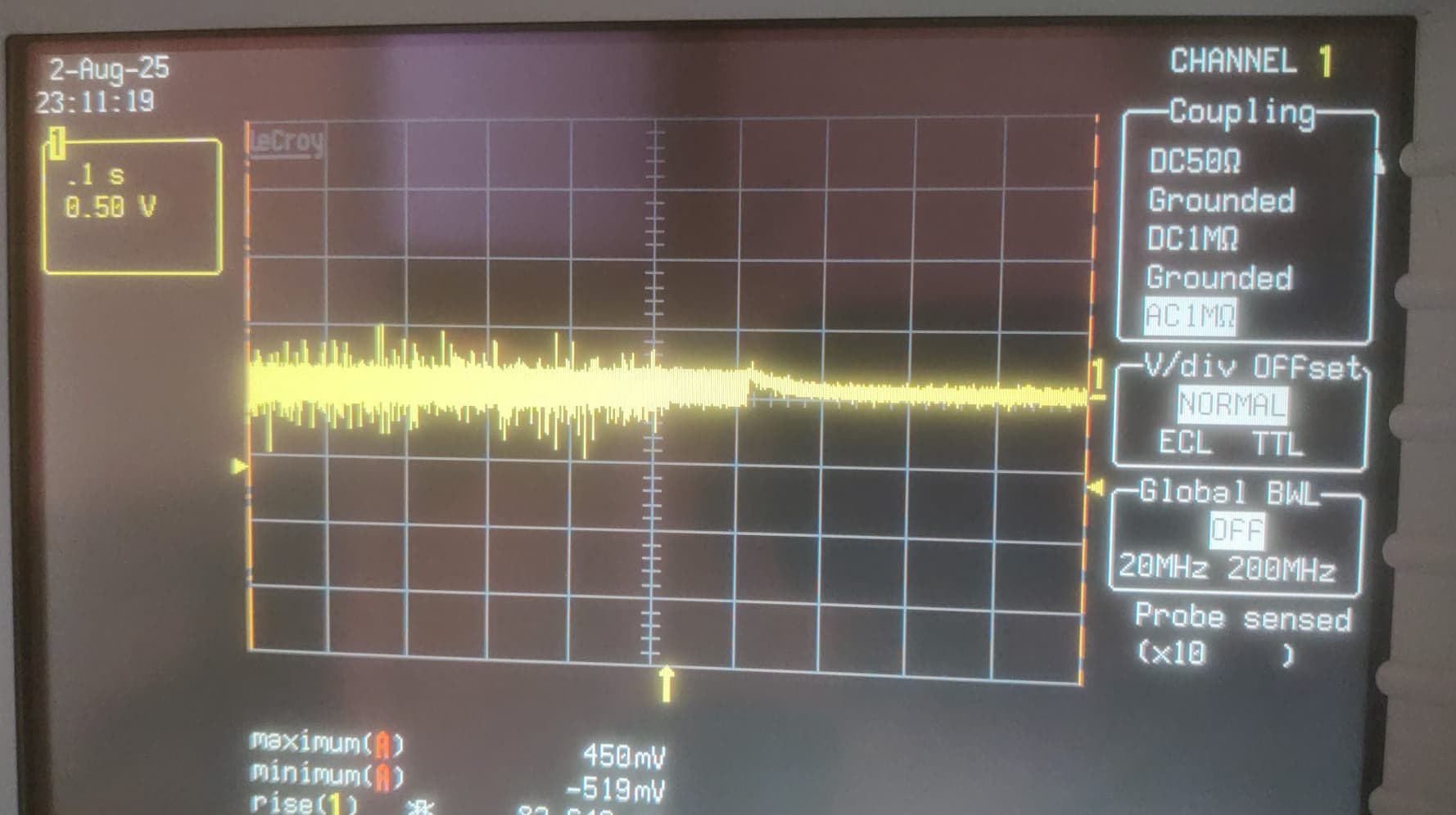
I calculated TOFF and PWM_FREQ so that it would lead to about double the default Frequency (at least thats what I hoped to achieve)
I definately missed that part which said PWM_FREQ is StealthChop Specific, but I definately see it now:
I tried this, because my original Motor had about half the inductance and I figured that I might run into some coil-saturation or something like this.
But I’m definately not a motor-specialist.
the TOFF and PWM_FREQ did however change nothing and I simply let them in because…
I remove them now as they definately should not be needed by now anymore
Also the Trinamic ticket is quite a good idea, I like that!
Before that I’ll try to get some more measurements, I’d like to monitor the supply Voltage of the Driver while Printing to see if any strange glitches are occouring…
Have to attach some shielded cable to the print-head and hook up an oscilloscope…
Fun tasks
I right now plopped a TMC2209 in the toolhead in standalone mode and had a 6-hour print printed with no problems. So the motor at least does not get randomly damaged while printing…
You can give it a try, as far as I understand, there should be no difference with standalone mode.
Just in a standalone mode, the driver would silently go to reset/error state.
I think that SPI driver diagnostics could be improved; at least it should be able to directly detect the reset.
But I’m afraid that could break something, it feels risky to rewrite TMC error checking =.
From my reading of datasheets, it seems more convenient to read:
GSTAT, check for reset (there is also an SPI_STATUS for that, which is now available to the code).
If reset: seems that nothing we can do, raise error.
If uv_cp: undervoltage, raise error.
if drv_err: readout DRV_STATUS, log, raise error.
But I’m not sure, it would actually improve the error reporting.
(Right now order is slightly different, and the logic is generic. So, we guess the driver reset).
=\
Also, the thing is that in your case code sees almost an empty field, which is strange.
OK, so the TMC2099 in standalone Mode definately works. If the Driver had reset itself during the 6h print it is not detectable to me.
I just hooked the oscilloscope up, shows voltage fluctuations from 18.3V up to 21.5V. But that is measured with about 2m unshielded cable so I don’t trust that measurement to be accurate.
over 3V voltage ripple would definately way too much. I’ll pick up some shielded cable and measure again…
In case of driver error, it is somewhat expected from the documentation that we could take an idea of “What happened?” from DRV_STATUS.
But it is empty, only the OLA flag, which is meaningless according to the documentation.
In case of reset, there would be no info why it does happened. Probably ESD.
well, I already thought about that, but actually didn’t think it was an actual problem.
Maybe it is afterall
I mean I probably could ground the motor housing to the Power-GND of my driver. It definately would not do any harm…
We definately have belt-driven system and the toolhead per design is electrically isolated from everything else (apart from the electronics, which are grounded to earth)
But I suspect the Housing of the Motor to be electrically insulated from the coils good and maybe its actually on the “potential of the printed parts” so to speak
If thats the root-cause than it would make sense that it happens spontanious as it would be affected by air humidity, pressure and temperature.
Oh and you would actually never be able to measure it, because as soon as you attach some sort of probe to it you would essentially discharge any builtup charge…
By “survive” I am assuming you are asking if they still work.
No the chip will not work/respond to UART communications; a TMC2209 needs both VCC_IO(which is what I think you’re calling “3.3V”) and VS(what you’re calling “V_mot”) to operate.
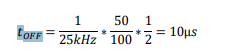
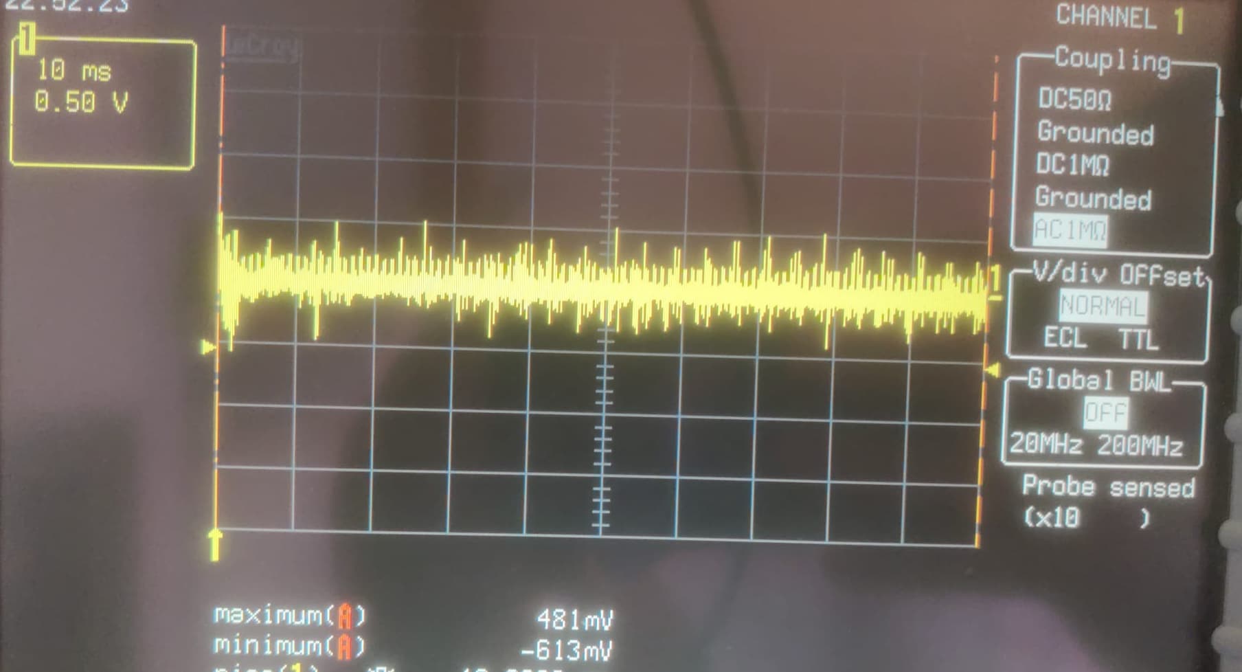
What I do see is about a 1V Ripple, which I is composed of some high-Frequency Noise from the stepper motor, as well as some lower frequencys from the heater switching (I increased the switching frequency drastically so that the additional capacitance have a greater effect)
Right now I’m running again to see if I can catch some particular drop in the motor-Voltage which triggers the stepper reset.
+/-500mV of noise/ripple is a lot. If you’re running a TMC2209 or TMC2130, according to their datasheets, that’s enough to cause errors in the sense resistors and cause the driver chip to shut down (which is what I think you were seeing with the OLA/OLB errors). Excessive ripple can also damage the internal charge pump capacitors.
What is current the Extruder/Toolhead power supply (and is it connected to anything else)?
What is the current stepper motor driver (Module or soldered to Toolhead controller)? What is the wiring to the toolhead? A diagram would be helpful.
Sorry for the questions but I’m not exactly sure where you are right now, there looks like there’s been a few configuration changes.
You should not need to throw capacitors on the line - you need to figure out the source of the noise/ripple.
yes, I defintely agree with you, randomly soldering caps onte the board does not fix the root-issue.
I’m also trying to get to the root issue here, but are in a state where I’m not sure where to measure or fix things.
And yes, I acnowledge that in that kind of situation my “quality of problem solving” often decreases and gets a bit “unfocused”
The tip with the ±500mV ripple is definately a good hint. I’ll bypass the USB-C connectors next and see if the ripple improves. If that does help (or maybe fixes the issue) I’ll order some quality Würth USB-C connectors to see if I can lower the connection resistance.
thank you all for staying around!
If this gets running we might have the first completely USB-C Powered Toolhead (which I think is awesome)
if this works reliably I also can go into the next step of development which would be to switch to the new USB-PD 3.1 standard wich is able to produce 24V (and 28V)