I try to set up an own built toolchanger with 5 tools.
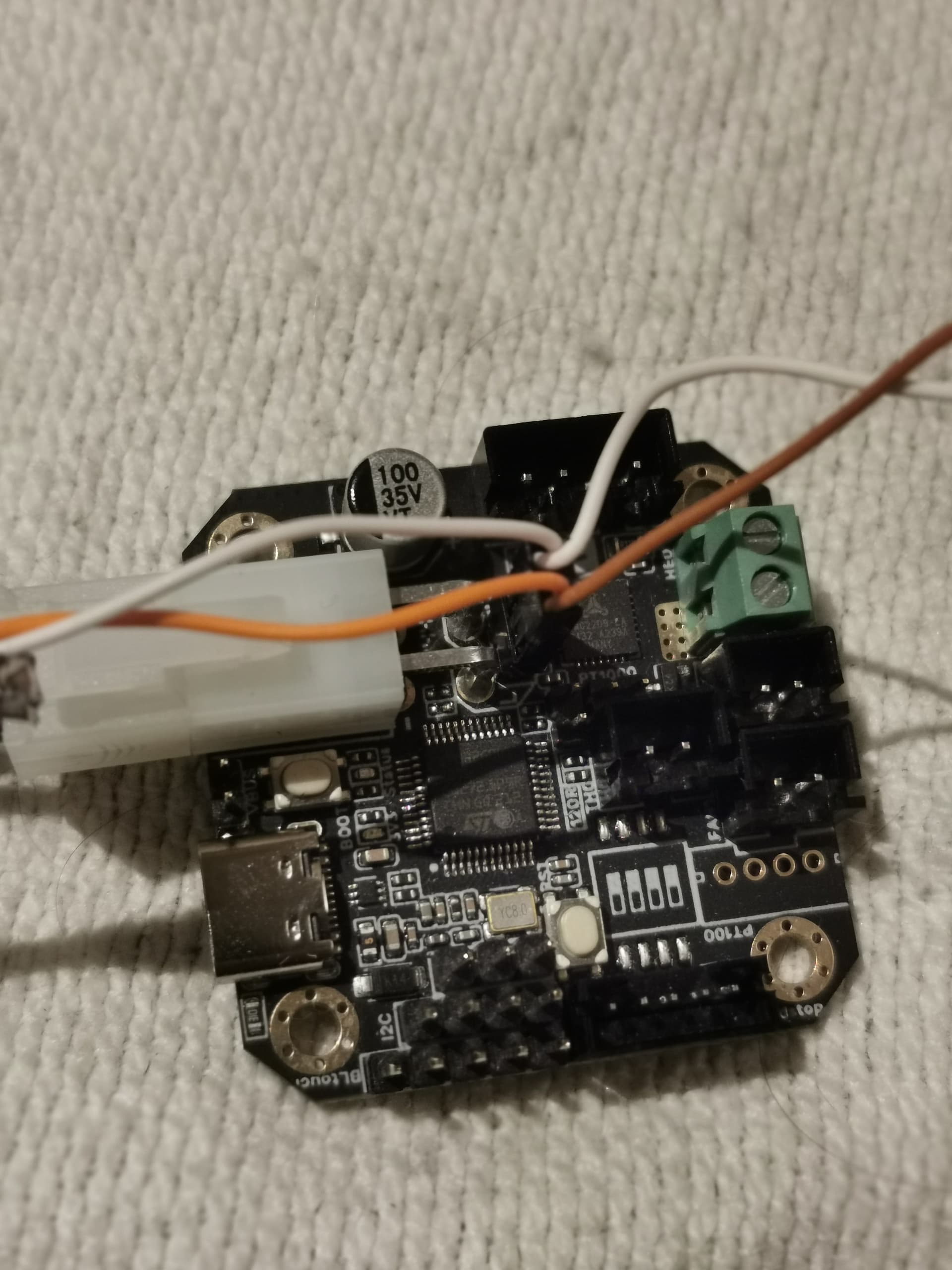
Each toolchanger has its own EBB42 board.
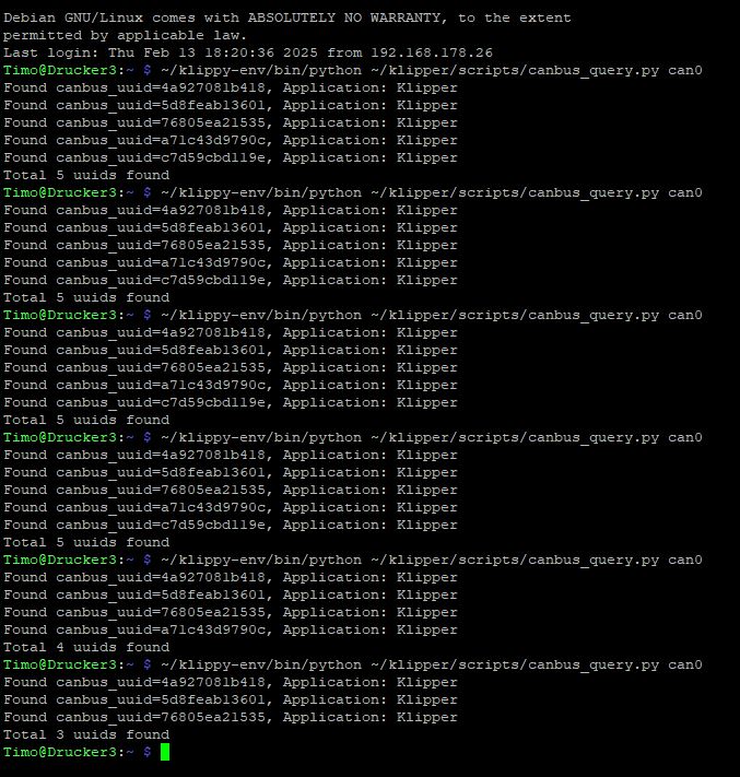
It is installed and when the printer is fresh started those 5 EBB42 boards are recognized over putty and the command:
Can you provide a clearer photograph/drawing of the CAN bus and how the EBB42s are wired? What is the total length of your CAN bus?
I can’t tell if the CANH and CANL are separate or kept together.
I’m also a bit confused at the datarate you’re working at - if you change it at the host you also have to change it at each of the devices on the CAN bus. That means you have to create new firmware and burn it into each of the EBB42s.
If five shows that’s great the test script is not the way Klipper communicates during normal operations.
Recommendations on your build.
Make sure you have the ID for each tool board because they’re more than likely not going report back in order down the bus. EX tool0 UUID, …. tool4 UUID
Go ahead and add the tool boards to your printer.cfg at the up as
[include tool0.cfg]
[include tool1.cfg]
[include tool2.cfg]
[include tool3.cfg]
[include tool4.cfg]
This will keep your brain straight
Add temp readings for the MCU for each tool board so you can see they are communicating
Make sure to temporarily change the min temps in each tool cfg to -250, this will hold off Klipper shutdown until you add thermistors.
FYI I’m building a Voron 2.4 with the four Z motors, A & B motors, and tool head all on CAN bus but the Zs will be on can0 and the A, B, & tool will be on can1.
I will be using EBB42s on the Z, PITB V2 for the A & B, and SB2240 for the tool head.
Using Seed Studio 2 channel CAN BUS RPi GPIO shield.
24V & 48V power supplies.
@koconnor can you give me your take on this setup?
That sounds cool but I remember @koconnor saying that X/Y steppers should be on the main controller board (which is a USB to CAN bridge and not on a CAN bus device) for best operation in terms of timing.
The last recommendation to make firmware updates simple use katapult as a bootloader on each EBB so Klipper and/or katapult updates can be done via the CAN bus not requiring any physical access to the boards.
What is the cable that you’re using to connect the CANH and CANL? Do you have a part number and datasheet?
From a practical standpoint, 9m is kind of pushing things - could you try 4m with 1m of cable between EBB42 nodes?
You might also try running your CANH/CANL connections through the Microfit connector rather than the header. The way you have it here, you have radiating stubs which are a few cm in length which isn’t great but shouldn’t be that much of a problem.
I interpret that as saying that the X & Y steppers should be on the main controller (which I presume is connected to the host either by Serial or USB).
The way you’ve written things up, it sounds like you are using the Seed Studio 2 channel CAN BUS RPi GPIO shield for your CAN interface.
The canbus_query.py is a diagnostic tool only intended to perform a single query, with the sole goal of identifying uuids that have never been seen before. The tool is known to not work reliably when there are many unassigned ids on the bus, and known to not work reliably if the command is issued repeatedly. Basically, when there are several unassigned nodes on the bus it can lead to nodes responding simultaneously to the same canbus endpoint id which is not considered valid for canbus messages and ultimately can lead to nodes transitioning to an error state where they will refrain from transmitting any messages on the bus.
If you’re bringing up several unknown ids, then identify them one at a time, and then once you know all the ids you can connect them all together on the bus, define all the ids in the printer.cfg file, and start up klipper.
If you’re trying to use the canbus_query.py tool for any other purpose than trying to identify the uuids for the first time, then I suggest you find some other tool as you are unlikely to have success with canbus_query.py.
There’s no requirement for USB anywhere. Placing all the nodes on canbus is fine. It is also valid to use two separate canbus buses on a single printer (eg, can0 and can1).
Unfortunately, I don’t think your proposed setup would work with mainline Klipper. Klipper supports multi-mcu homing, but it is not currently possible to mix multi-mcu homing with a multi-stepper axis if those multiple steppers are on separate mcus. So, you wouldn’t be able to define an endstop or probe that could stop your four Z steppers because you’ve setup your Z steppers on multiple MCUs.
On my voron2 ( GitHub - KevinOConnor/voron2-mods: Voron2 printer modifications ) I run all four Z steppers on a single stm32g0b1 board, and use three separate huvud boards for X+Y, X-Y, and toolhead. I also use the stm32g0b1 board as a “usb to canbus bridge” node with the other three nodes attached to the resulting canbus. Thus, my rpi just has a single usb connector to the stm32g0b1, and everything is tied off of that. You might want to consider something similar.
I’ve never used the “Seed Studio canbus shield” you’ve referred to. So, I can’t speak to that. In general I prefer USB to canbus adapters over shields.
In general, I’d prefer to discuss these types of things on the public forum (as others may also be interested).
Ah, yeah - I missed your original “ping” in this thread. As you’ve cited in my off-line message, you can put all the nodes on canbus if you wish, and you can use two canbus buses if you wish. The mainline Klipper code doesn’t fully support multi-mcu multi-stepper Z though.
As for timing, as a general recommendation I’d try to designate the mcu controlling X and Y as the main mcu (ie, [mcu] in the config). It’s not a requirement though. For example, on my voron2, where I have separate MCUs for the X+Y and X-Y steppers, I designate the stm32g0b1 board that controls the four Z steppers as the main mcu. I’ve never noticed an issue with it that way.