Hi There!
I was just tired to measure my gantry corner values (although it seems to be good enough to have a coarse guess) and was thinking of calculating these values out of a simple measurement. Why is the world better with this? You do not have to do it manually and it should be much more accurate, so the QGL should converge faster.
Basic Idea: You measure by probe two X-Positions of the Table. First (measuring#1) at some position of the Z-Axis(es) and second (measuring#2) moving one side of the gantry a little up (maybe you have to move two motors, to be discussed below!). From the difference, you should now be able to calculate the “left” distance from Z-Axis to the edge of the table. You may do it again for the other side, let J2 be static and move J1 (or both J1 joints).
Here is the basic sketch for 2D approach:
J is a joint from the gantry to the Z-Axis where J1 is the “left” joint and J2 the “right” one. J1,1 is the position of J1 at measuring#1 and J1,2 J1 at measuring#2 (stays the same for J1, is different for J2).
P1 is the Position of the “left” measuring point (for measuring #1 and #2), where Tx1 in known (X-Position counting from left edge of the table)
P2 is the Position of the “right” measuring point (for measuring #1 and #2) where Tx2 is known.
d is the wanted distance of J1 from the table edge
X1 is the position of P1 from J1
X2 is the position of P2 from J1
h is the (unknown) height of J1 or of the probe
Y1,1 is the measured probe value of Position 1 at measuring#1
Y1,2 is the measured probe value of Position 1 at measuring#2
Y2,1 is the measured probe value of Position 2 at measuring#1
Y2,2 is the measured probe value of Position 2 at measuring#2
Now the calculation:
We use the intercept theorem for solving this.
we see that (Y2,2-h) is the height of a triangle, that has its left point in J1. Line 1 shows this behavior of Y1,1 and Y1,2. The result is in line 3 an equation for h
Since the same approach can be done for measuring #2 and h is the same, you get equation line 2 and 3. All values of the middle bracket are known from probe values, so we define this to be “a”.
From the definition of X1 and X2 we now can calculate d=f(a). Since we know all values of this, d should be solvable. q.e.d.
Question: Does this makes sense to you? Is that function helpful enough to implement it? Is it already implemented? Is it solvable also for 3d gantries? May it help somewhere for bedslinger kinematics?
Any comment is welcome.
Interesting proposal although I’m not sure why you need a really precise measurement - I’ve found being within 5mm on my Voron to be good enough.
The only real concern I have with this approach is that it assumes/requires that your height measurements are nuts on. I’m trying to figure out how critical it is and I want to do a bit of math with the CoreXY printer I designed (as I know the value for “d” precisely which is 80mm). The printer has a bed (“Table” in your analysis) size of 220mm square and I’m probing 5mm from each edge.
Let’s put together some numbers to check the formulas above:
Tx1 = 5mm from the left side of the table
Tx2 = 215mm from the left side of the table
h = 9mm
Y11 = 9.86mm from the bed surface (Using 0.58 degrees that gets you 12mm for Y12)
Y12 = 12mm from the bed surface
Y21 = 10.44mm from the bed surface (Using 0.97 degrees that gets you 14mm for Y22)
Y22 = 14mm from the bed surface
This gives you a “a” value of 3.45 and, plugging in the numbers for the final value of “d”, you get 80.0mm, so the algebra looks good.
Now, let’s assume that the Y11 was high by 0.05mm (which I think is realistic for most probing approaches) then “a” would be 3.77 and plugging in the values for Tx1 and Tx2 you get a value of “d” which is 70.7mm which is probably worse that a “rough” measurement.
It’s a interesting theoretical approach but, I think, in practice you’ll find that it probably isn’t acceptably accurate.
Hmmm… But Y11 should be always much larger than this since is is the position of the connection of the Z-Axis to the gantry… At least for the Voron this is some cm… anyway, it is just a proposal and the PO should see, if it is worth a try…
I had the feeling, that the QGL converges not too fast, if the distance is only “guessed” since in the code (as far as I read it), the correction values are added without any damping factor. Znew = Zold + correction. For my mathematical feeling, it should be something like Znew = Zold + 0,8*correction but I can be wrong and maybe I looked at the wrong place inside the code…
So in my setup, sometimes the values of the four Z-Axes are corrected in different directions for small stepsizes (step n: +correction for Axis Z1 and step n+1 -correction for axis Z1) and this should not be…(but: does no greater harm). I will have a look at this, maybe I looked at the wrong correction values at the command line during QGL…
If not of any help, this was a nice academic exercise 
But Y11 should be always much larger than this since is is the position of the connection of the Z-Axis to the gantry…
Sorry, I don’t understand this statement - Y11 is “d” plus “Tx1” distance away from the Z-Axis to the gantry according to your drawing.
I chose the values based on my printer. I designed it with the restriction that the gantry supports could not be at an angle greater than 1 degree (which works out to 7mm but in practice, I’ve set the QGL parameters to reject required movements greater than 4mm). I know it can’t be “some cm” for my Voron 2.4 - I think the range of less than a cm on the far side is quite reasonable for a practical distance.
I agree that the QGL algorithm could be improved - it’s fun to watch the first couple of times going around but after five or six you just want it to get done. I’ve increased the “tolerance” range for my Voron 2.4 significantly from the default of 0.0075.
Tx1 is the distance from the heatbed’s “left” corner to the measuring point. X1 = d +Tx1, the complete distance from the gantry corner.
Y1(x) is more or less given by the statement “sample_retract_dist: 2.0” in the probe section, I think + of course the measured difference to the heatbed. So the value should be sample_retract_dist+distance in most cases. I correct myself it is some mm not some cm! My first idea was, that Y1(x) is the height of the X-beam of the gantry over the heatbed, but since most of this height is constant and you see, that all constants will be removed because of the comparison of the two heights for mneasuring #1 and #2, it doesn’t matter so much. The “true” measured value for the voron (according to the output of the command line during probing) seems to be “sample_retract_dist+real distance” >> 0,05mm.
I think this approach could be quite accurate… 
Maybe we can simplify the measuring if we treat it as a 2D measurement: Let’s just link both “left” Z-Axis and both “right” Z-Axis. Ob, both “left” might have an Z-Offset and the “right” ones, too. But it seems to be of no effect for the calculation of d-left and d-right.
After calculating these, you turn everything by 90deg to “right”, so “D right 90deg” is now the distance from the backside of the gantry (picture: the motors in the back) to the backside corner of the heatbed. Doing the same calculation now, you should get the correct "d"s for the distance front/back of the heatbed, too. It will in any case be better than my hand-measuring, since it is not clear, where the joint of gantry-Y to gantry-X physically really is (Belt? Bearing? in between?). This maths will show that…
1st run: Z+Z1 are “left”, Z2 and Z3 are “rigth”. The turn 90 deg “right” so 2nd run Z + Z3 are “left” and Z1+Z2 are “right”.
(I took this from
https://docs.vorondesign.com/build/startup/images/V2-motor-positions.png)
And think of the Z Gantry alignment for bedslingers. Here you often don’t even see that connection point.
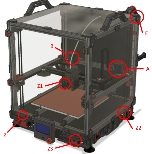
Sorry, I took my mobile to take this photo, so it is completely distorted! BTW: see my 10mm insulation below the heatbed! Remember the discussion about the PID? That helps to speed up heating a lot!
I got another question: Who is the PO of Klipper? Or is this a group? just for my personal information…
Sorry: too much text as usual…
Okay, I see what you’re saying exactly now but I still feel like a small error in measurement can result (surprisingly) large errors in results when you are going across a few hundred mms.
I was already thinking about the 2D case and breaking it up into individual pieces the way that you did and was thinking about using the bearing and not the belt/anywhere else would be best.
Regardless, I think the idea is worth pursuing to see how practical it really is.
FYI, there was a discussion on this at Z_TILT improvements .
-Kevin
I read most of the discussion from your link, but somehow it was abandoned and not finished? Was too complex because of the implementation? I did not get this right…
The main problem was that I got next to no reaction. I had one more tester besides the one in the PR, but it didn’t work out too well on their machine. The implementation isn’t too complex, but it requires numpy.
As the topic has come up twice in the last few weeks, I can try to revive the PR. Not sure how far those parts of the code have moved in the meantime, though. My own installation of Klipper is still at that point, so it might take some time.
Maybe we could thing of putting all together: QGL might be a 3D Version of Z-Tilt compensation if you look closer to it? At the end the target for both is to align a gantry parallel to a reference surface. If you “lock” Z1 and Z0 and on the other side Z2 and Z3, you get something very similar (as a target) as Z-Tilt-Compensation in my eyes. Think in requirements not in solutions… The next guy is coming up with a three-point gantry compensation and let’s think some Milliseconds…Yes could be done with the same math, too… Maybe this is worth a look…
Yeah, I don’t see a problem to extend it to more than 3 motors. The basic idea is to deliberately tilt the bed in a few directions and calculate the intersections of the various combinations.
On my machine z_tilt_adjust always converges on the first run.
I have to confess: I have no idea, how the Klipper development really works. Is there a “team” or is there a PO (=Product Owner) who defines what to do? I do see the Github page, but the structure is not known to me. Could maybe illuminate myself?
There is some info on contributing to Klipper at Contributing to Klipper - Klipper documentation . Klipper is an open source project and thus the changes that are made are heavily influenced by contributions of contributors.
-Kevin
OK, so you start with a pull request, so the coding is already done. So no “no-coder” can contribute and there is always the “danger” that your code will not be “pulled”. So more or less the core dev team decides what to pull? I never worked with an open source project, so this is new to me.
So if I want to promote the topic, I have to write some code or look for support to do so. I thought there are some resources to implement promising ideas (i don’t know, if this is one!).


