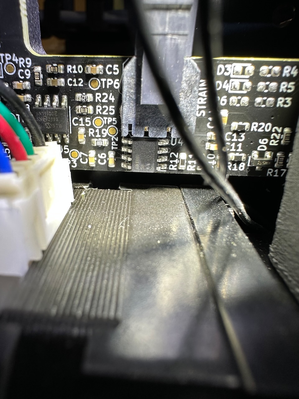
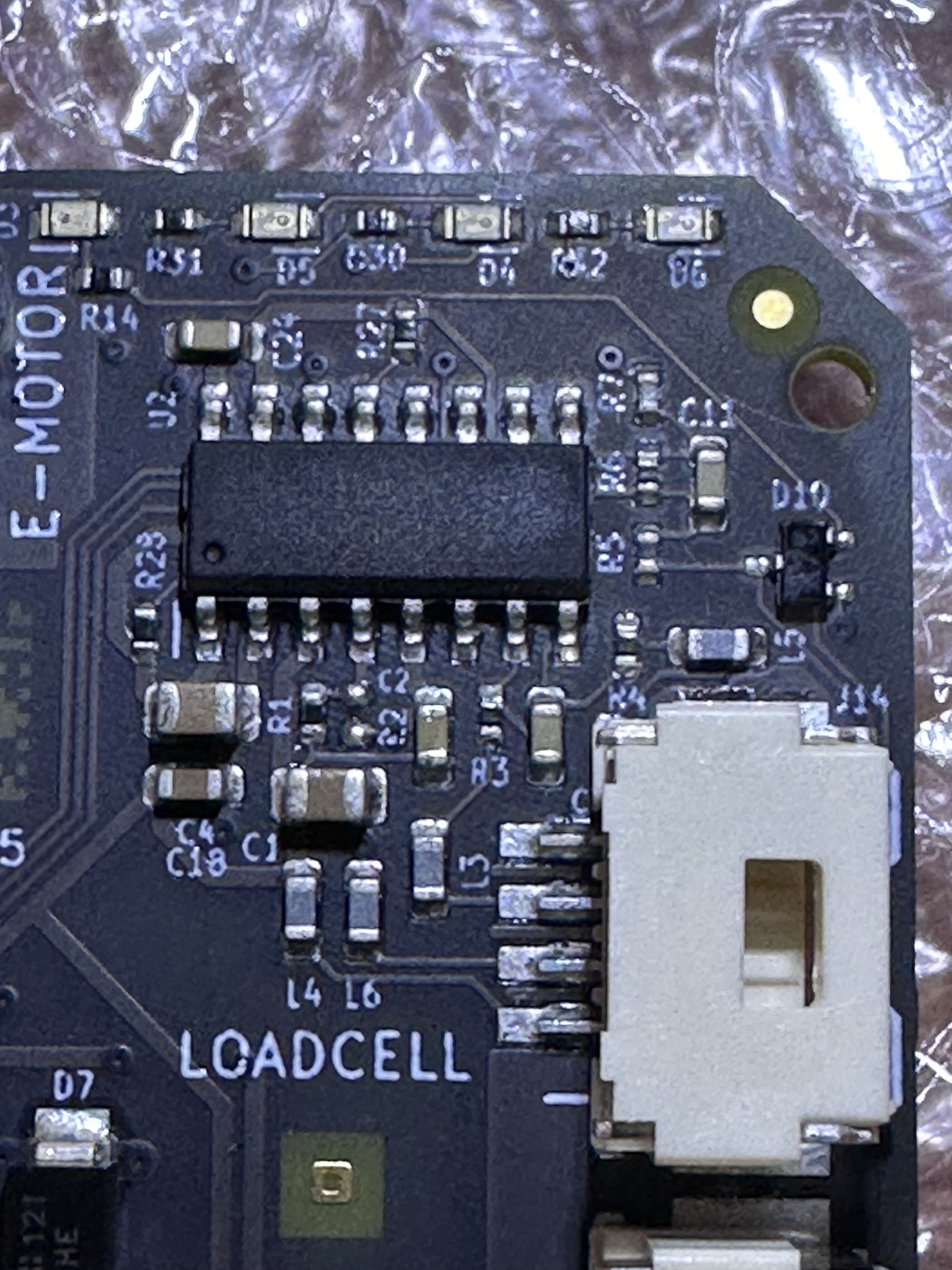
Here is a close up of that chunk of the board:
I haven’t tried to produce an electrical diagram, I figured I’d wait till they open sourced it.
Here is a close up of that chunk of the board:
I haven’t tried to produce an electrical diagram, I figured I’d wait till they open sourced it.
Are both S0 and S1 pulled high? Beacouse in the picture it looks like S1 is connected to DGND.
Can you take a picture of the backside of the pcb?
The back side is no help, it’s just a solid plane with some vias. My guess is it’s 3 or more layers.
I just got my MK3.9 upgrade bundle with the MK4’s main board. There is a second ST490AB on that board and its hooked up to the pins for the one on the LoveBoard. So I need to find one of these on a breakout board that lets me connect it up to some I/O pins.
( Also, surprisingly, the ST490AB is like $3 each! That’s more than the HX717 is!!)
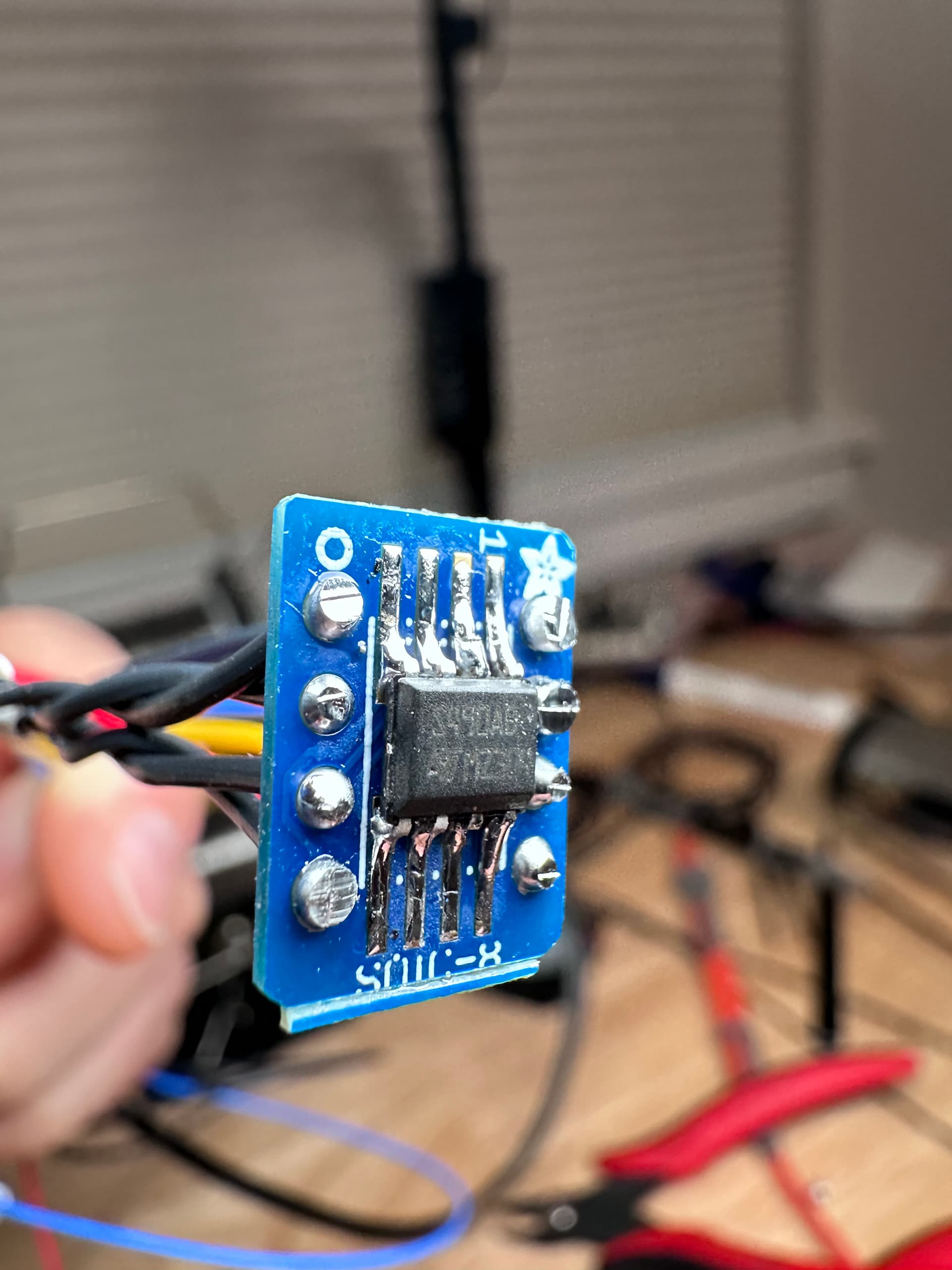
Edit: Adafruit has SOIC-8 breakouts so you can combine that with the ST490AB chip for a working solution
I have a the Pantheon HS3 which uses a custom slice heat break incorporating a load cell and their own board which has a couple instrumentation amps (MCP6N11) - I don’t know the special sauce with their board but I don’t think you need to use a load cell amp to get the job done. The setup is +/-.005.
Looks like a beast!
As far as Amp + ADC or just an ADC goes… all of the ADC’s of this type have adjustable gain. Sometimes thats enough for the application and sometimes it is not. It depends on many factors including the sensitivity of the strain gauge, the sensitivity of the load cell, the number of bits in the sensor and the noise floor.
Usually these things are designed as systems: ADC + strain gauge + load cell.
To be sure, there is no amp in the Prusa system, but that HX717 has a max configurable gain of 128 and thats the mode they are using.
Success:

Prusa Love Board with HX717 talking to klipper. It homes, it probes and it quad gantry levels. I have the ST490AB on a breakout board and did the twisted pair wiring as per the spec. (looks gigantic but smaller than a postage stamp)
I didn’t try to hook up the filament sensor, but everything else on the toolhead is functional, so it can print. I just need to work out the rotation distance and current for the E stepper.
The load cell reports a massive range of ~85Kg when calibrated. So that’s a lot of sensor range going to waste. That’s why we need all these bits. You wont get lucky with the physical system being tuned to the sensor’s range. Be prepared to give up 80% of the usable sensor range.
I’m curious why we haven’t explored the idea of placing more robust load cells on the bed instead of the toolhead. We all appreciate lighter toolheads, and positioning the load cells on the bed could theoretically reduce complexity. This approach allows for greater design flexibility since we aren’t confined to the compact size of a toolhead, making it easier to work with.
I think we will try it. Certainly the K1 is doing it. I’m biased towards toolhead sensors because they can also probe in X/Y for IDEX and Tool Changer machines. Plus they get continuous monitoring of filament force which should end up helping us detect spaghetti.
Messing around in CAD again:
I put the features on the end to support the Revo heater blocks and nozzles. I have no idea how to get it manufactured though. Those features are so small I guess you need a custom form tool ground to even cut them. I’d have to go to a machine shop with prints with tolerances on them to really communicate what I need done.
absak asks
I’m curious why we haven’t explored the idea of placing more robust load cells on the bed instead of the toolhead.
If I may respond. This is an area I have spent a lot of time exploring and testing many combinations and my conclusion is that underbed sensors can be a mess.
The problem is that Z probing is a dynamic event, and the sensors, whether only one or several, will be at different distances from the nozzle contact. Leverage effects alone will mean that the time from contact to detection can change by a factor of two over a short distance.
If I may give an example: A circular bed with three sensors equally spaced on the circumference is probed at the bed centre, and the sensors will trigger if one or more are pressed down by a certain distance, say 100 microns. In the dead-centre case, they will all trigger at the same time. Just away from the dead centre, one sensor will act as a fulcrum, and leverage will cause the sensor furthest from the fulcrum to trigger at half the distance, say 50 microns. It gets even worse with two sensors acting as the fulcrum, as the multiplication is now 3:1 and the trigger will occur at 33 microns.
Add to this the almost inevitable difference in sensor sensitivity, and you get areas outside the triangle of sensors where the sensitivity can go negative. Yet another problem is that the time taken for a signal is not the speed of sound in a metal, as the plate is vibrating like a guitar string; the propagation time for these transverse waves can be in the millisecond region. Additional to this is the effect of reflections from the edge, which can attenuate or even cancel a signal before it reaches a sensor. You can see this effect on “Chladni plates” e.g https://www.youtube.com/watch?v=lRFysSAxWxI&t=7s
Underbed sensors can work, and many have used them successfully. Small, very rigid beds with sensors fully outside the bed are best, and a low bar for acceptable variation goes a long way, but for high sensitivity and accuracy other options should be explored.
Mike
I made a short video talking more about my implementation of a strain gauge endstop.
Hello!
im new to the subject but what about load cells on the Y axis itself for the corexy machines? bewteen the linear guides and the y axis?
would be less of a variance than the whole bed but still the leverage issues of course
but would still have the benefits of a simpler and lighter printhead that the usual loadcells might make heavier and more complex?
Hey, I think this is actually a good idea. I have currently setup underbed sensors.
I think you could add the loadcells on the y-carriages using two half bridges. I don’t see any reason that shoudl not work.
I have just configured toolchanging and I’m asking myself the question how I cloud automate the z-offset-calibration.
When I home using virtual_z_endstop and I run probe after that, I usually get this result:
// probe at 200.000,200.000 is z=0.113452
I think the value of 0.11 is due to the fact that the homing does not use your probe algorithm - it moves until the probe is “triggered” and thats the value. Fair enough - I think it’s good for getting a home position.
My question is, can I write a macro that does use the result of probe and write it in my printer config? That way, I could store the tool offsets in my config file.
Can I write a macro that uses probe and that changes the z-offset?
Yes, you could write it to [save_variables]. You can store whole objects in there so you could keep an object for each tool and use whatever settings you need when tools change. I made a post about this a while back.
Yes…
I have a mcro on the test machine that can do this:
[gcode_macro _SET_OFFSET_FROM_PROBE]
gcode:
    {% set z_offset = printer.probe.last_z_result | abs %}
    { action_respond_info('Probe Offset calibrated: %.5fmm' % (z_offset)) }
    SET_GCODE_OFFSET Z={z_offset}
However, you have to call this macro from the macro with the PROBE call in it. You cannot put everything into 1 macro. Because of how macro evaluation works, the result of the PROBE is never available to the currently executing macro.
(Macros use a templating engine, your macro is a template and behaves like one. All variable substitution happens in 1 pass when the macro starts, then the code executes)
So
i found this topic very interesting and want to help out and bring new input in this thing.
I thought about the load cell designs since a couple days ago and think about many ideas…
I searched for proper sensors and strain gages and my conclusion is that the sensors which are basically for industry applications are way to big. And the few that has a compact design are crazy expensive.
The “problem” with the strain gages are that these things are based on stretching and compressing and needs always elastic supporting material with well known mechanical properties. The printed parts of plastic will not act similar as metal parts and in my opinion so it is difficult to apply and use strain gages correctly in this situation without the specific knowledge…
So after researching about all the stuff I found a very promising sensor solution for our situation:
datasheet
shop-link:
https://eu.robotshop.com/products/capacitive-force-sensor-8-mm-100-n-22-lbs
This is usually for robotic components.
It’s a capacitive push force sensor that has a very compact form factor and is very affordable priced.
plus it has a very good interface options like
3-wire Simple Analog and I²C interface and additional open source software.
It’s all well documented.
The sensor element is ultra thin and sensitive and comes with different measuring ranges.
Finally looks good what do you think ?
So I start thinking how we could install this type of sensor in the tool-head.
The changes should be subtile as possible cause i don’t want to ruin the modularity of the beauty EVA system… I create a first rough design with 2 sensors 8mm-100N for the extrusion force and one more for the probing force.
I split the “hotend_rapido_fi” mounting part into two separated parts and integrate the sensors inside the flux of force. The idea was to get some kind of a “bridge” or wing part which is safe connected to the hotend and has two bearing areas on the sides. So if the extruder is pushing the filament through the nozzle it creates a down force on the two bearing sides their sits the two sensors on exposed sockets inline the flux of force.
The two sockets acts as indexing bolts and should prevent the bridge part to move sidewards and hold the unit place in theory…
Because the sensors can measure only pushing force on the upper side sits a third sensor in the gap between the “front_universal_fi” part and the bridge part.
At the probing process the nozzle slightly touches the bed and create a slightly upside force against the upper sensor.
hopefully that all makes sense to you
I’m curious… Has anyone run across a film type gauge witha hole in the middle? It seems like it would be ideal for placing between a v6 hotend and extruder…
hello!
not sure if anyone is still trying to make their own strain gauges but i have done some FEM testings and research, and i have a question, should the strain gauge be accurate / repeatable at 1 gram?
considering ADS1220 ADC with 1k sps and max gain the noise itself is 0.70(4.01) and with turbo mode at 2k sps it would be 0.82 (5.81) RMS(peak to peak) meaning the lower half of the bits are just noise and useless (enob would be at 15)
what would the loads /be at usual 3dprinting loads, my plan on the loadcell is not to use it for extrusion force but only for the bed leveling
Hello everyone! I have designed a practical strain type hot end pressure sensor that can output both analog and trigger signals simultaneously. This module is an analog circuit that can output noise free differential voltage signals
Analog Hot End Strain Sensing Trigger - Developers - Klipper
Hello, instead of using the load cell in the hotend, I am designing a solution in which I will place 3 sensors of 5kg each on the table, using Arduino and HX711. This way, in addition to using it as a sensor, we can measure the weight of the object to be printed, allowing us to evaluate when a problem occurs during printing.