The data sheet lists sensitivity to 20N, which, if my calculations are correct, should still be within the typical 300% safety margin of deformation during a 5KG extrusion force.
I ordered one and hope to get to experiment with it a little later this month…
I really want a toolhead load cell concept that can be manufactured with a minimum of processes so its economical to test out. We will have to do a lot of iterations. Ideally just a flat block of laser cut aluminum with minimal to no machining. SendCutSend can do these for minimal cost.
I was idly sketching a 3D Printer concept in CAD and going over where I could mount the load cell and came up with this idea:
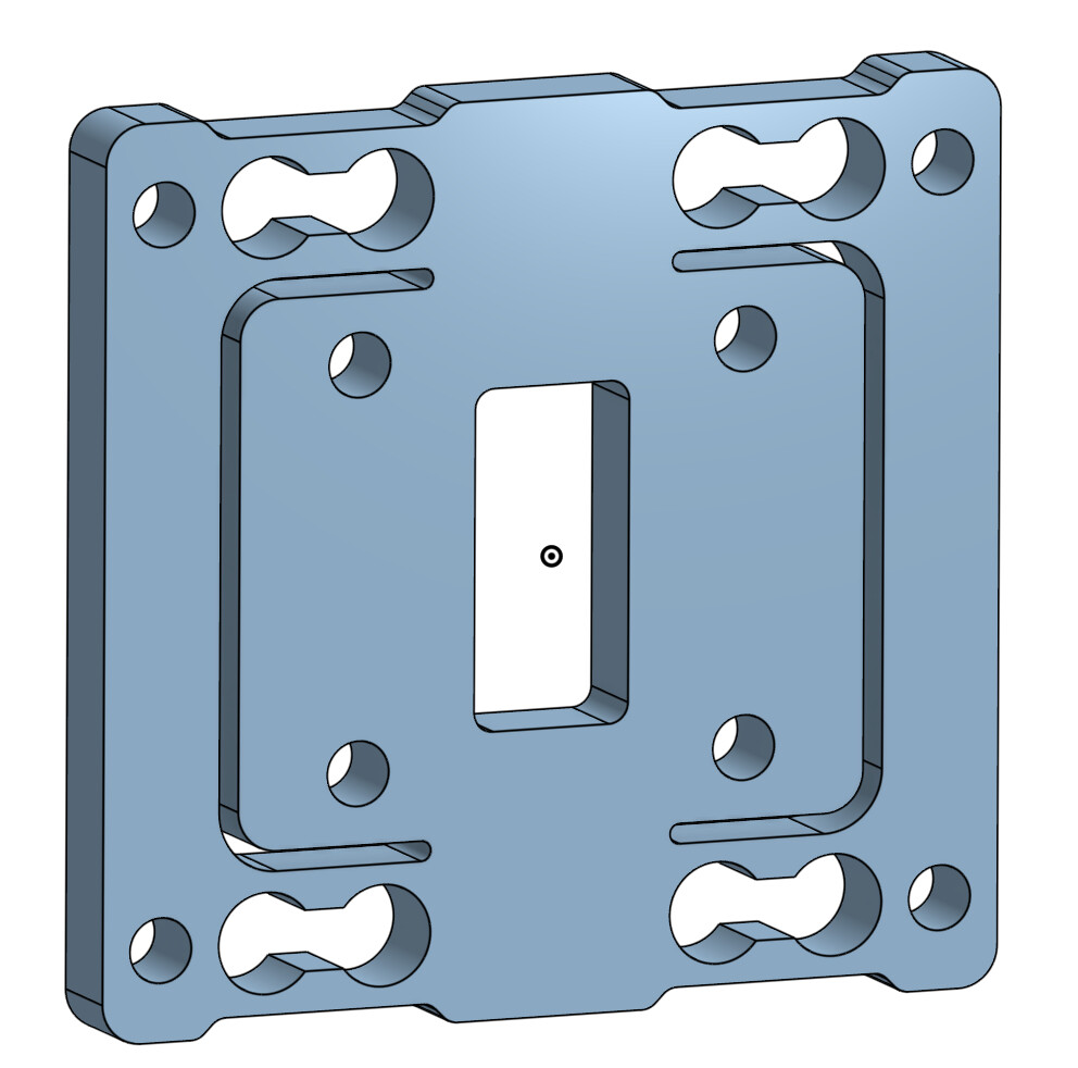
Its a plate that attaches to an MGN12H carriage via the 4 central holes. A 3D Printed part would be attached to the back to grab the belt teeth on a Core XY printer. The hole in the middle allows the belts to exit.
There are 4 outer 3mm holes to attach the toolhead to. So this is a “toolhead adapter plate”. You can use whatever toolhead design you can adapt to this.
There are 4 “dog bone” flexures but you only need to put a strain gauge on 1 of them. Its just symmetrical to carry the load symmetrically.
Negatives:
weight: this would add ~20g to the toolhead
Extrusion force cant be measured. I guess one fix for that would be to extend the structure upwards and attach the extruder to that.
I wanted really tight tolerances at those split lines to save as much space as possible. The easiest way to manufacture that is to just split the entire thing into 2 parts. Then you have easy access to all sides in 2 separate processes:
The outer silver/flexure part can be made out of Aluminum on a CNC machine with a 3mm endmill. It requires 4 holes in 2 ends now but at least there is lots of places to grab the part in a vise. No wire EDM needed. It could also be 3D metal printed. The outer holes are tapped so the toolhead can be mounted blind.
Added a feature to limit the travel of the flexure. If the toolhead crashes it will bend the X axis before it permanently deforms the flexure.
The inner part is 3D printed plastic. That means its easier to include the complex geometry to grab the belts against the face of the MGN12 carriage:
It also means your free to modify that part to suit your needs. E.g. adapt it to MGN9, or some other mounting.
The whole contraption goes together with 4xM3 bolts from the top/bottom. That adds some possibilities, like using these holes to mount the Extruder as well.
This looks manufacture-able and adaptable to existing hot ends and extruders.
interesting idea.
But if I understand this right, this works only if the x-rail is mounted sidewards on the x-beam like a voron style printer. If the x-rail is mounted on the top of the x-beam like a Vcore for example this design needs a change or implmented in the toolhead design between the frontplate and the top part that is attached to the rail carriage.
You could make a different plastic block to go in the middle that attaches to a top mounted rail. But I think you are right. For best space efficiency you could probably design something different for a top mounted rail.
I don’t like the top mounted designs because the cantilever distance to the nozzle tip is increased. (center of rotation is the center of the rail)
Yeah I know what you mean, but mind that the part fan is mounted on the backside of the toolhead and the motor of the extruder is placend above the x-rail, so the overall center of mass of the toolhead is more in the near of the middle of the x-beam, so the summary load ont the x-rail is more “pull downwards” compared to front mounted rail there you have summary more a “hanging mass”, that pulls the rail carriage sidewards if you know what I mean…
But no matter for sure we can create two version for these different designs
The used ADC is not broken out as an SPI device but communicates via an enable pin to enable or disable the probe and an output pin that acts as a regular switch or endstop.
The logic and cool functionality developed by @garethky seem not applicable.
Overall, it looks like a big missed opportunity. I hope I’m wrong.
hx717 were not supported at first either, this is not a problem at all. The cool thing here is that there is a free implementation and a factory-made hotend with an integrated cell.
I think the hotend with attached load cell makes a very good impression. Might be worth a try to hook it up with the garethky electronics.
ADS131M02 ADC supports an SPI interface, nothing else. The electronic board from FLY is just a bad joke. But the ADS131M02 ADC looks like a nice candidate for load cell applications.
Adding support for an additional ADC type is not too difficult. But if there is no SPI then it can’t be done. But maybe there will be some other board that you can plug the load cell into for full integration.
Their doc page doesn’t exactly look promising: Introduction | FLY Docs
Still taking 3 samples and a tolerance of 50 microns! I’ll wait for some PROBE_ACCURACY results.
does anybody have experiences with ‘printed plastic’ strain gauges?
I’m up to give that a new try…
See the first try here - i gave up, since i didn’t understood the mechanical part. My design was far too sturdy and i did not use the ‘stretching by bending’ method so my readings didn’t generate any output.
Bending can be close to nothing, its the strain that matters, i havent had time to keep working on the projcet, but run FEM and finetune it, with a good geometry you can maximise strain and minimize bending. Also depends on the straingauge size, since straingauges take the average of the strain that they see in the whole area under them so if you have a smaller straingauge you can make the strain consentraion spot smaller and get more accurate readings with less actual displacement. Ofcourse you also have to take into account the material limits so it is strained but wont brake
Hi, I’m new and found my way here searching for load cells and klipper.
On topic, the Sovol SV06 Ace/ Ace Plus series use a load cell sensor that works well, seems fairly robust and inexpensive.
Key Aspects of the SV06 ACE Load Cell:
Function: Used for automatic bed leveling and calculating the Z-offset.
Mechanism: Detects pressure directly on the nozzle as it touches the bed.
Design: The sensor components are located on a flexing plate directly above the hotend.
Components: The system is integrated with the printer’s Klipper-based firmware.
The white “flexing plate” is a c-shaped profile connected, via the wires on the left side of the plate, to the can bus tool head board. The ceramic heater/nozzle is sleeved into the heat sink at two points; a cylinder that fits with the heat block and a stainless steel “pipe” with an inner diameter large enough for 1.75mm filament.
Sovol has published the design under a GPL license. Maybe some of the elements could be adapted into the current project.
On a side note. The reason I was searching is that I’m interested in setting up MainLine Klipper on the SV06 Ace and the OEM firmware uses custom python3 based load cell code. It is hardwired to sample at 10hz.
I’d like to have an advance plan to configure the load cell in Mainstream Klipper - ideally pulling in the factory calibration values. I could probably jig up a scale to calibrate but I’m not sure it has to be dead accurate in terms of actual weights - just repeatable..
Can someone point me to example setups in Mainstream Klipper?
Support for the HX711 is in mainline. There is also documentation and commands for calibrating the load cell from scratch.
I don’t recommend using the HX711 for probing because your probing speeds are severely limited and your accuracy will be low. Its good for weighing filament. The HX717 is what you want for probing. But if you are stuck with what Sovol gave you then , its supported.
I’m glad you responded - from what I see in the forum, you’ve been the main driver behind the load cell code.
I’m new to Klipper configuration and am trying to learn how to setup the hx711 for the SV06 Ace. I don’t want to hi-jack this thread so I started a new one.
I’m one of many who are not happy with Sovol’s interpretation of the GPL license, they have not disclosed a few key aspects that prevent a mainline klipper install. Sovol also does not plan on any more firmware updates for the series. Many have bork’d their systems with Moonraker/Kiauh upgrades and fret about unaddressed CVE’s in the Debian code.
Most of the components are being tackled - using the stock hx711 is the remaining piece.
The load cell, as implemented on the SV06 Ace/Ace Plus, works slowly but does give acceptable results.
Hi! New to this, trying to figure out how to make a load cell leveling printer for a portable printer I am designing. You said not to use the HX711, but I can’t seem to find a HX717 breakout board anywhere. Also, how exactly should I design my toolhead for this system? I still haven’t chosen an extruder or hotend, I just know it will most likely be on a MGN12C carriage. Thanks so much!