Printer Model: Davinci 1.0 pro 3in1
MCU / Printerboard: BTT SKR 1.4 turbo & raspberi pi pico (rp2040)
Host / SBC: pi 4
klippy.log sorry, it was too big so I zipped it klippy.zip (1.9 MB)
so a couple knights ago I fried the analog input pin that was controlling my thermistor, I double checded this via a physical resistance meter on the thermistor and via checking all of the wiring.
the btt skr 1.4 tubo has 2 of said pins, but when I got it the first one was already not funcitoning for whatever reason,
I also have a pi pico 2040 which has ADC pins so I figured I’d solder a header to that and just use it there. specificaly i soldered to pins 34 and 33 which are an adc2 pin and a ground pin based on this graphic,
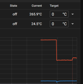
what you’re seeing in this graph is the typical floating point error resting space for my motherboard, sitting somewhere around 430 C (not actually) then once plugged into the pico it drops to around 250C
I decide to send some power to the hotend to see if it will decide to work… it goes up, I set the temp to 0 to turn off voltage and the reading remains relatively the same,
the pico pin only registers in the software under gpio28, is there another pin name i’m meant to be using to denote that i’m trying to use the adc pin? any help would be greatly apreciated
First off this is the wrong forum. You don’t have a Klipper problem.
That said… Does the Pico have an internal pull up resistor on the ADC pin? An ADC usually measures VOLTS. Without a pullup there is no signal coming from the thermistor. You need to construct a voltage divider using a reference resistor and the thermistor.
I don’t get how this is the wrong forum but go off queen. the question I asked was if there were differen’t names for the pin that would be used in klipper.
as for pullup resistor… I feel very stupid for not having checked this. be back shortly
a pull up resistor did bring the temp down, and make it do things, however it’s still not accurate to where it was with the original configuration, which was accurate previously, I will do some testing and maybe some calibration later
Can you provide a wiring diagram of how you attached your thermistor (and pull up)?
I presume that you’re attaching the rPi Pico to the rPi 4 host via USB? That would make the connection something like an SB2040 Toolhead controller and wired like:
Along with the wiring diagram, could you include a screenshot of your rPi Pico make menuconfig screen?
You should also include an updated klippy.log.
I think when you described the peripheral board as a “raspberi pi pico (rp2040)”, that confused things a bit and made it sound like it wasn’t something that could be addressed here.
I removed it because I learned that it has it’s own internal one, else I just took 3.3 from my external power supply 10K to the adc pin
however that SHOULDN"T be required
Now, you can use GPIO26 or GPIO27 - it doesn’t matter.
According to the rPi Pico schematic (chrome-extension://efaidnbmnnnibpcajpcglclefindmkaj/https://datasheets.raspberrypi.com/picow/pico-2-w-schematic.pdf) there is a 200Ω resistor in series from 3.3V to the ADC_VREF output, so you need to add 200Ω to whatever resistor value you use for your circuit.
Now, a 4.7k 1% is the typical pull up resistor used with Klipper - in this case you need to set your pullup_resistor in your printer.cfg to 4900.
If you’re using a 10k resistor, it’s probably okay but you’ll have to make sure it’s 1% tolerance or better for correct temperature readings.
I actually plenty resistors, i have a fishing tackle box… or 3… of electrical components that I picked up from a thrift store.so… 4.7 is perfectly okay
this worked perfectly, and I’ve gotten the resistance within .7%, which is pretty good. that shoudl be a difference of just a couble degrees at most, which is more than close enough.
Look at your wiring as well as the thermistor (I’ve had a couple of thermistors that perform like that and things straightened out, literally, after replacing them).
wiring should be good, though there are a number of connectors in the way, we are rebuilding a davinci 1.0 pro and attempting to use the original hotend pcb