oh, sorry didn’t noticed.
1 Like
Quite close to the centre of the bed. Between the heater mat and the aluminium plate.
It is quite precise due to the aluminium plate sucks the heat away from the mat.
1 Like
There is no dual sensor implemented to control bed temperature, not in klipper, if you are concerned about safety, most of my colleagues have a klixon, a kind of thermal switch, that opens at a defined temperature, mounted in series with hotbed itself, there are also no auto resettable ones, maybe you want to use such kind of device, in my case, all my printers have a relay based system, in order to completely cut the power to the printer if something goes wrong, in your case, when you talk about big differences in heat up time, from my point of view, the only you need is to re adjust the hotbed PID values, as I can deduct from your words you really have no problems inside the machine, my recommendation is not to try to have a double temperature control on same heatbed.
Sorry to bother you again but there are answers, that I can not believe, I’m not calling you liers, I’ll explain myself, the temperature reported by a thermistor, is never the bed temperature, really, is the temperature measured inside itself, then, if you have a very big bed, and the sensor is in a corner, you’ll never could think that you have same temperature everywhere in your bed, this is a statement, second assumption, if you have a decent infrared meter or whichever you have, and measuring at thermistor tip, you have a temperature ten degrees different of the one you have in your Klipperscreen, Fluid, Mainsail, or whatever you use, you simply have defined wrongly the sensor you’re using, this is absolutely common, the most of the people have a mounted sensor, a physical sensor, different to the sensor defined in Klipper, you can do a check, even with cold printer, changing from Generic 3950 to a good ATC Semitec 104NT-4-R025H42G, just changing this definition and re starting again, you could see at ambient temperature, differences from one to two Celsius degrees, imagine in the opposite part of the curve, where the resistive values are much smaller, and at same time much more significant, from my point of view, I’m not a master of anything, but I was 40 years working in industry, I was dismounted my first industrial extruder at 16, working and studying, the best is to place the sensor at the center of the bed, use thermal paste , kapton tape to hold it in place, the auto adhesive cotton isolation blanket, and of course, to know which sensor are you really using, and to define it perfectly in your klipper section, make a good PID tunning, and forget it, as an example I could tell you, that in My slicer, I use the same thermal settings for same filament in all my machines, the only secret, is because all of them are measuring just in the same way

and finally some help related thermistors, and the way of calculate or define them:
[thermistor PT3-25E2-S2_Gabriel]
# Ready to work
temperature1: 25
resistance1: 98630
temperature2: 135
resistance2: 2371
temperature3: 200
resistance3: 550
[thermistor PT3-25E2-S2_Gabriel-2]
temperature1: 25
resistance1: 98630
beta: 4300
#beta calculada: 4124.25
**********************************************************************************
Thermistor definitions
**********************************************************************************
[thermistor Thermistor_Escrich] # Under test, whole range evaluated
temperature1: 25
resistance1: 98733
temperature2: 137
resistance2: 2408
temperature3: 250
resistance3: 226.25
#Beta: 4054.69
[thermistor Thermistor_Laureano]
temperature1: 25
resistance1: 100000
beta: 3950
[thermistor Trianglelab-NTC100K-B3950] # Looks good, even under mechanical problems
temperature1: 25
resistance1: 103180
temperature2: 150
resistance2: 1366.2
temperature3: 250
resistance3: 168.6
Trianglelab-NTC100K-B3950
EPCOS 100K B57560G104F
Generic 3950 <---------------------------
Thermistor_Escrich
Thermistor_Laureano
ATC Semitec 104GT-2
ATC Semitec 104NT-4-R025H42G
Honeywell 100K 135-104LAG-J01
NTC 100K MGB18-104F39050L32
SliceEngineering 450
TDK NTCG104LH104JT1
===============================================================================================
@Escrich Thank you for spending time on the response, so here is mine.
- I’m not super concerned about safety, but trying to take it seriously, because i sometimes print overnight.
- I also have a relay on AC input, that moonraker can shutdown in case of an emergency.
- I have a few singe time use thermal fuses on hand, but i was not able to find a good way to secure it on the pad itself, and screwing it to the bed pate have no big sense to me, since in case of thermal runaway adhesive on the pad may fail first.
- I’m not a professional, but i think i have good enough basic understanding of electronics, and how the temperature is measured on both hardware and software sides. I agree that what you are saying can absolutely be the case, but i still think that we have a real effect there.
- I understand how to use IR thermometer, it’s limitations, and agree that it’s very hard to get correct absolute reading even when using it right. I don’t have much trust to mine, and use it with caution.
- I realize that there is no ideal thermometers in the world. But we, as mankind, managed to achieve incredible results using our non ideal instruments, by thinking and creating smart measuring techniques.
So, to check myself, and check the theory, i decided to do some experiments.
Experiments
First I started the printer, and decided to look how the heating up curve looks like.
(bed surface thermistor is a control input)
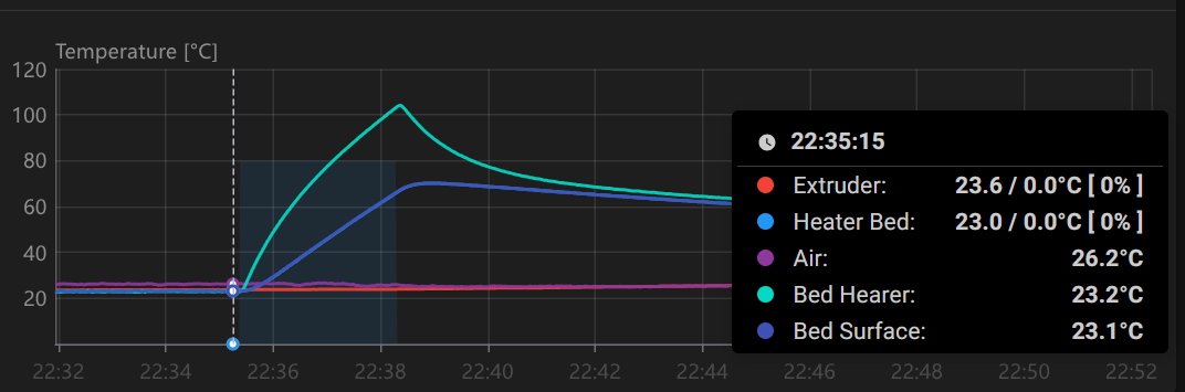
We can observe, that on idle, both thermistors are in a good agreement between each other.
Then during heating up the difference becomes massive. I even had to turn it off, because heating pad exceeded 100C.
After i turned it off, the bed started to cool down naturally, but the bottom side of the bed is insulated, and the top side is not, so there is still a temperature gradient. It’s smaller than when the heater is on, but it’s still there.

As we can see, surface now reads measurably lower. And that depends on temperature.
Ok, but what if you were right, and the difference is explained by different linearity of the thermsitors. (i mean linearity after a software compensation, since thermistor by itself is very non linear sensor of course)
Then i had an idea. I took blanket from my sofa, folded it a couple of times, and insulated the top of the bed with that. Than i turned the heater on (now on a lower target) waited a bit, and turned it off.
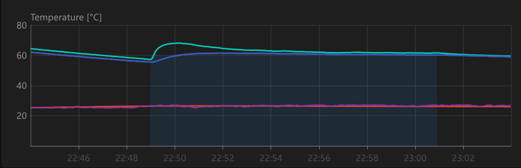

Now we can see, that even with the heater on, the difference became smaller. And when the heater is off, thermistor reading become almost identical, but now it’s on target temperature.
So we can now say that it’s not so much a linearity difference issue.
But the most interesting thing happened when i removed the blanket.

As we can see, after removing the blanket, very pronounced divergence between readings can be observed again.
Conclusions
Despite I agree, that our measuring equipment is far form precise, we can conduct, that the effect do actually exist, and not just a result of measuring error.
I’ts also aligns with my understanding of physics involved.
I can not conduct the experiment on higher temperatures, because my blanket is not fireproof, and i’m not ready to test what will happen when it’s heated to 100C+ (label says to wash on 40 ![]() ), but i think it’s safe to say that it’s not a measurement error either.
), but i think it’s safe to say that it’s not a measurement error either.
And as soon as we agree, that what we observe is mostly the actual physical effect of temperature gradient across the bed assembly, we can rule out that it can be fixed by tuning the thermistor definition, or PID coefficients on the current implementation of the regulator.
P.S.
You printer builds are looking super clean and accurate, I can only wish mine looks that good.
And thank you for challenging me to do that experiments. I probably wouldn’t do it without that.
2 Likes
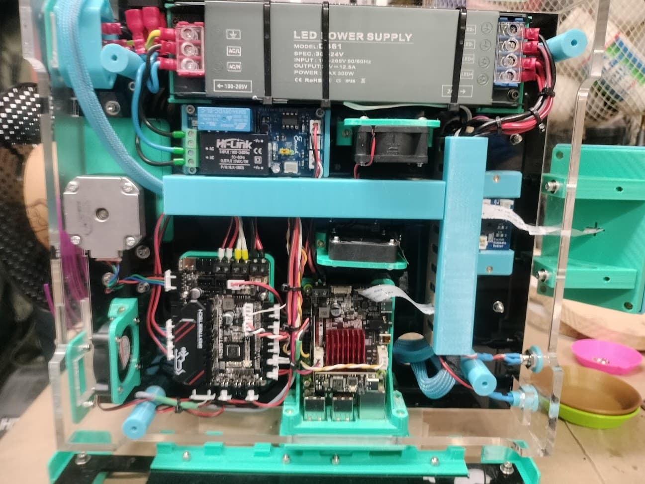
You did a good job, my pictures are just for you to see some thermistors placed wherever, mainly in both power supply units, in one of them, three plastic straps are only to hold the white cable, in the other case, look for white tape next to a small green piece, every fan in pictures is running in a temperature controlled way, but the small ones over mosfets, that only works when the mosfet is working
I dont know if what I say is right, but you can connect the bed thermistor to a pin on the motherboard that is ment for the hotend thermistor. That pin should have a pullup resistor. You can play with that resistor value to “corect” the temp that you can measure at the surface of the bed. From what I see on my BTT MantaM8P the bed thermistor dedicated pin does not have a pullup resistor, and neither the [heater_bed] section in printer.cfg does not have a pullup_resistor option, and I did not try to see if it accept one. But worth a try?
That’s a bit off topic so I’ll put it under the spoiler.
offtopic
That’s interesting, I didn’t think to put it on the power supply. Do you have multiple of them? And what cutoff temperature are you using?
I don’t cool my ssr, it’s rated for something like 25 or 40 amps, and i’m switching less then 4, so i think it’s ok.
Btw, just interesting what is that thing with lots of caps on it? do you have additional power filtering?
The issue is that observed shift is not constant. After yesterday’s experiments I’m pretty sure that it’s caused by the assembly thermal resistance, and that meas that the shift is proportional to the heat flow thorough the assembly. (Same as the voltage drop on the resistor is proportional to the current). But the amount of heat flow depends heavily on how much power is dissipated from the bed surface, which strongly depends on environmental factors. So it can not be statically compensated.
Meantime, today i needed to do some printing, so i reverted to heater thermistor for the bed control.
And here is how the situation looks during the print:
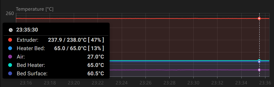
As we can see, when everything is stabilized long into the print, it’s close to 5C difference for 60C target now.
And by the way, If you are interested why it’s almost 240C on the extruder for PLA print, it’s because I have a rapido uhf style extender, an full cooling, so the same effect as on the bed is most likely taking place. I just don’t have a themistor over there.
I’m wondering, what if you set the beds sensor pin to the surface sensor? Then you could configure the heater pad sensor as a thermistor with a max temp so the heater pad doesn’t get too hot. Then you can try a PID tune on the bed.
1 Like
The issue here, is that max temp on the heater or sensor is a protection, not a limiter. When that temp is reached klipper will just fall into error state, and will require restart. That will make starting print impossible.
The PRs i attached a few messages above, were exactly about implementing limiter functionality, which would be a perfect fit.
2 Likes
Sorry, but I disagree. I completely go with the last statement from 3dcoded. Use the sensor placed on top of the bed to trigger your relay, which controls your AC silicone heater pad and ignore the sensor in your pad. You should get a correct temperature on your thick bed!
Regarding safety, in Klipper reference is stated from Configuration reference - Klipper documentation to heater_bed:
…
max_temp:
#   The maximum range of valid temperatures (in Celsius) that the
#   heater must remain within. This controls a safety feature
#   implemented in the micro-controller code - should the measured
#   temperature ever fall outside this range then the micro-controller
#   will go into a shutdown state. This check can help detect some
#   heater and sensor hardware failures.
…
So you should be perfectly clear regarding safety! And you also have your
Reading through the comments in the first mentioned PR from here Dual Loop PID by rodrigo2019 · Pull Request #5972 · Klipper3d/klipper · GitHub I can understand why koconnor refused to accept the PR. I can’t comment the influence on heating performance.
1 Like
As i mentioned, that was the first thing i did.
As you see, the pad exceeded 105C while surface was around 70, and lines continues to diverge. And it’s not a coldest day by any means.
I don’t want to overheat the pad. And I don’t want to gamble if it will trigger the protection, or I’ll be able to start a print that time.
As for the comment you mentioned, I disagree with that. I think the configuration is pretty simple, it’s just 2 additional params. Also the applications are not only limited to the beds, It will benefit any other case where you are interested in heating something which is not directly on the heater itself. It can be for example larger extruders, or some powerful chamber heaters which can damage itself, or it’s surrounding.
2 Likes
Ok, just now I understand your concerns. Can you please post a link of the pad specifications?
It’s one of the cheaper, probably chinese ones. I bought it from my local retailer, and it didn’t specify any temperature limits. I saw similar enough ones on aliexpress and amazon, which are rated at about 150 - 200C.
Mine also had a 3M 468MP printed on the adhesive protection sticker, and according to datasheet, it’s rated to 149C long term and 204C sort term temperature resistance.
However, I can not be sure that the genuine adhesive was actually used, and it’s not a chinese trick, since it’s mostly impossible to check and proof after sale. And there are tons of much lower spec adhesives over there.
Also, my bed is insulated on the back with that typical self adhesive foam insulator pad, which is in direct contact with the heater, and it’s adhesive is not labeled at all.
I print quite a lot, and currently have 2721 print hours on that machine, since i updated it to klipper about 2 years ago. So even if it might be ok to leave it as is, that’s to much factors i’m not sure in, to feel comfortable about that long term. And I can’t say that it’s really necessary to push tings to their limit it that case.
With these figures
you shouldn’t be concered.
As I explained, I don’t have much reasons to trust that specs, and want to be more conservative when we are talking about regularly potentially overheating something.