Ok, I understand those concerns. So, you could start a new PR mentioning all your concerns.
Well, generally there is a complications about power density and thermal mass.
As example your bed have roughly 0.8w/cm2, where others can have something closer to 0.5, for example mine (IIRC) 1000W/(42*42)=0.56w
So the simple duct tape, is to limit a bed power a little.
Second, there is a combined sensor, which can combine 2 sensor outputs and try to stabilize system to some degree. It will work and would have some offset of the real target temperature.
Third, is to, well, make control loop more sophisticated.
Mine suggestion here can be this: RFC: Cooperative Heaters predictive control by nefelim4ag · Pull Request #6837 · Klipper3d/klipper · GitHub
I do not have setup with 2 bed thermistors, but in my mind.
There should be a heater control over the bed thermistor, to reach the target temperature, and there should be a template duct tape which will limit power as long, as heater would try to approach some high watermark.
Like if heater temp < 130, then 0, else -100500 or some any other back propagation if you like.
Hope that helps.
1 Like
Hi. Yes, limiting the power of course will work, but that defeats the purpose of having a powerful bed heater.
As for combined sensors, i already tried that. The issue with that is that it doesn’t have conditional control. It only have max min and mean. In max it’s the same as heater sensor is in control. In min it’s the same as the surface sensor is in control. And mean is in the middle, it doesn’t allow to avoid overheating, while also not fully fixing a temperature error issue.
As for feed forward, it’s a useful thing to improve response time, but I don’t see how it can fix the situation here. Correct me if i misunderstood you PR. As for me, it’s not solvable for regulator, until it’s only accounting for one of the temperature sensors.
I’m considering that. Of course I can just reopen the PR, but my python programming skills probably won’t be enough to meet such a big project code quality standards, if modifications will be needed.
As I mentioned above, feed forward allow to do whatever you want. Even decrease or increase power by accounting to the phase of the moon, literally.
So you simply do the PWM control over the surface thermistor.
And then template allows to offset the power in any direction.
As example, by reading the heater temperature and by outputting the negative value.
Which will overdrive the PID output, and allow to disable or limit the heater progressively.
The actual control algorithm is up to you, I suggested the bang-bang above.
It can be proportional, so (T_surface-T_heater)/10.
The pid output is 0..1, so +0.5 would try to increase PWM by 50%, and -0.5 would try to decrease.
PID can internally output any float value, so you can blend any float value, like -9000.
Hope that helps.
Oh, wow, i didn’t notice it accepts templates. If so, It’s very powerful tool, and can fix the issue.
However, I’m a bit scary that it’s to powerful to be merged. It allows to really screw up things for not advanced user. And as for advanced, there are possible performance concerns, since as far as i understand it runs on the PID loop frequency, and there is no protection form doing stupid things.
But i still think it’s cool. It opens big possibilities.
As far as my understanding goes, I do not overdrive the min/max temperature things, or verify_heater things. So there is no safety difference. You can put stupid pid values and have similar opportunity to ruin something.
From performance standpoint, pid is running every 300ms, and so does the template. For architecture reasons they are running independed from each other. (It tries to render before pid, as best effort).
So, I doubt it puts any more strain than fan templates.
Thanks.
Hi people. Today i finally had a chance to test the pr from @nefelim4ag
Here is the tests
So before changing anything i did a control test by heating up to 70C:


As we can see it took 5 minutes to heat to 60C and the best it was able to achieve is 64C in about 12 minutes.
Then I switched to the branch, added simple proportional regulation to my config, and did a PID autotune.
[display_template bed_limiter]
text:
  {% set bed_heater_temp = printer['temperature_sensor bed_heater'].temperature | float %}
  {% set max_temp = 100 %}
  {% set range = 5 %}
  {% set proportional_damping = (bed_heater_temp - (max_temp - range / 2))/range %}
  {0 if proportional_damping < 0 else proportional_damping * -1 }


[heater_pc heater_bed]
macro_template: bed_limiter
Then I repeated the same test

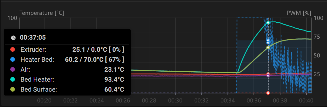

As we can see now it reached 60C in 2.5 minutes, and then it’s target temp of 70C in about 3.5 minutes.
As for me it’s quite noticeable improvement!
It was a bit of overshoot for about 1C, but it’s not that much critical.
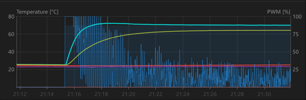
However, despite limiter action was present, it was not very pronounced. So i decided to repeat the test with higher setpoint of 85C to look into limiter in more details.

Now limiter action is much more visible.
Then i decided to test protections. I can confirm that both overtemperature and rate protections are working fine.
It’s also possible to check rate protection, by setting limiter lower that target.
Issues
-
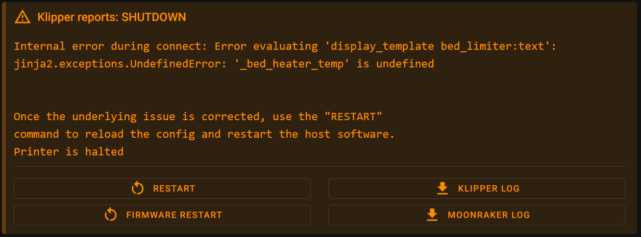
Templates are a bit hard to write and debug, because if error happens in the template, it’s not clearly communicated in the mainsail klipper status error, it only shows some generic one, and you need to go to the log to understand what’s the issue. If possible it would be nice to improve it to make it similar to other config errors.
-
Looks like the regulator output is not 0 to 1. While testing protection, i witnessed that situation:
Limit was set to 65C but even on 80C it allowed some PWM output. And when i did changed the setpoint, it even allowed full power. And that happen while i applied around -3.5 to regulator output. -
After i switched to the PR branch and did a PID tuning, I had wired issue saying “Can not update MCU ‘mcu’ config as it is shutdown” but it resolved itself after i pulled in latest master. I was not able to reproduce it, and log did not mentioned anything useful, so that may not be related to that feature.

Conclusions
Despite there is some minor issues, I think it works great overall. I really like the possibilities that that PR it opens, and it’s not limited to bed heating. I don’t know how to lobby that to be merged, but I think that feature definitely worth to be in the main branch.
4 Likes
Thank you for testing and awesome graphs everywhere.
Yes, fixed.
Yes, it is intended right now.
The current formula is:
co = self.Kp*temp_err + self.Ki*temp_integ - self.Kd*temp_deriv
co += self.heater.get_pc_correction()
bounded_co = max(0., min(self.heater_max_power, co))
So we calculate the PID, adjust the output with correction, and only after bounds are applied.
It is done so when there is positive power feedback, PID can still overdrive it (assume we try to put too much power by simple multiplication formulas, even if we do +1.5, PID still can reduce the power).
So, it would be pretty simple to do not-so-accurate positive compensations.
But when we are trying to limit the power of the heater, this ability makes it slightly more complicated to do. Because PID can still overdrive the -1.0 correction.
So, I just assumed it is okay, because most of the time we can simply do -9999.0.
I’m not sure what the best solution here to be honest.
UPD:
Fixed, now they both can output now -1..+1, so they can overdrive each other if it is required.
So, pwm +1, and correction -1 (like avoid overheating something) → 0
So, correction +1, and PID -1 (like preheat for some reason) → 0
I would guess it is just a fluke.
Thanks.
1 Like
Hi. Thank you very much for fixes. I’m out of printer now, but will get back to it in a couple of days to test, and will get back with the results.
I think the last update with the -1 … 1 range is very useful, because even if user is not trying to limit the regulator, that allows to impact output by constant measurable amount.
Before that, impact effect amount depended on the internal state of the regulator, which as far as I understand is not directly accessible to the user, making it hard to understand and use. The same impact of 0.5 could have led to a completely different effect. We probably wouldn’t be able to describe such behavior in the documentation, if we want to merge it. Updated approach is much more clear, at least in my opinion.
1 Like
Hi again. It’s been quite a while, but i finally had some time to check @nefelim4ag updates.
Meanwhile, i updated my heating control algorithm to allow for even faster heating, buy pushing regulator output to full power till the bed is heated to target temp and difference is still large. That is useful when heating to lower temps in my case. Now it looks like that:
[display_template bed_limiter]
text:
  {% set bed_heater_temp = printer['temperature_sensor bed_heater'].temperature | float %}
  {% set bed_surface_temp = printer['temperature_sensor bed_surface'].temperature | float %}
  {% set bed_target_temp = printer['heater_bed'].target | float %}
  {% set max_temp = 100 %}
  {% set range = 5 %}
  {% set proportional_damping = (bed_heater_temp - (max_temp - range / 2))/range %}
  {%if proportional_damping >= 0%}
    { proportional_damping * -1 }
  {% elif bed_surface_temp < bed_target_temp - 1 and bed_heater_temp - bed_surface_temp > 20 %}
    1
  {% else %}
    0
  {% endif %}
It will cause some overshoot, but not to big, since part of it will be dampened by heat soaking in that case, and I think such behavior is even better for that particular application.
So, let’s get to tests.
Template validation test
I intentionally did a mistake in my template, and now can confirm that the error is highlighted during klipper startup:
Heating test
That’s simple, let’s heat to 80C and look into the charts:


As we can observe, heater was at 100% power until it reached 100C. Than, limiter did it’s job, and successfully kept it under control. And it did it much more precise and clean than it was before fixes.
We can also note that the PWM values dispersion is quite low for some time after it reached the limit, and that’s the confirmation of the proportional damping is taking place over 100% regulator output, until the point when PID controller started decreasing power by itself.
As for slight overshoot on surface temperature, as I explained before, it’s probably the result of my control logic and some amount was expected.
It took slightly less then 5 minutes to 80C, but it’s significantly colder in the room that time, and analyzing the PWM chart, I would say it did it as fast as possible, accounting for limitations i set myself.
Protections test
Same as before, while bed was still warm, i set the limiter temperature lower than it actually is, and turned the heater on:

Now, limiter didn’t allowed any power to be applied (which is exactly what’s expected), and I got heating rate protection activated.
I also tried max temp protection, and can confirm that it’s still working fine.
Conclusions
After running a few tests, I can confirm that fixes are working as expected.
- Template validation is improved, and now works as expected.
- Now we have an ability to make corrections to regulator output not only for direction we want to push it, but also for predictable amount of impact we want.
- Heating rate and max temp protections are still working fine.
I didn’t find any additional issues that time.
Overall I really like the functionality it opens. I not only tested it as a limiter now, but also tried pushing it forward, and now i can get my large thick bed to the PLA print temps in about 2 - 2.5 minutes.
It also has much wider applications than simple limiters, and I don’t see any downsides it brings in, so i definitely recommend that PR to be merged.
p.s.
Want to thank @nefelim4ag one more time, for the time and effort he put into that PR.
Also, big thanks for everyone who participated there. Despite 3d printing is actively commercializing last years, it’s people like you, who bring us to the point that such cool tings are now possible. I’m really happy to see that it’s still the force driving us forward.
1 Like