Hey,
I was looking for config file on a Bluer plus and i felt on you post. From what i have seen and read, the config files from Sappphire machines seem to be a bit the same.
On Marlin, the 4.3" screen is a problem too.
Have you finally found a solution? by the way with mainsailOS or Fluidpi i don’t think that the screen is usefull.
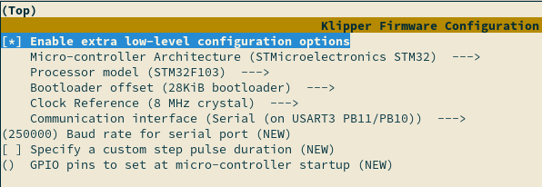
On “communication interface” waht should i use if i’m in standalone? i haven’t done the modification on the TMC2209 yet.
[include client_macros.cfg]
[include client.cfg]
[include mes_macros.cfg]
```What does it refer to?
simple question, are you french? 'cause "mes_macros" sounds like.
Hi All!
I have been trying to install the Klipper firmware in my TT Bluer+ using different parameters, but in most cases I get the message “TFT Update 100%” on the printer screen and when I restart the printer I see the message “Booting” forever.
It is a Bluer Plus v1.2 - 5 Drivers TMC2209 to run Klipper firmware.
[include shell_command.cfg]
[include fluidd.cfg]
[include mainsail.cfg]
[include macros.cfg]
[include timelapse.cfg]
[include my_other_config.cfg]
#[include ebb42usb.cfg]
#[include pitb.cfg]
#[include buttons.cfg]
#[include probe.cfg]
#[mcu]
#serial: /dev/serial/by-id/usb-1a86_USB_Serial-if00-port0
#restart_method: command
#baud: 250000
[mcu]
serial: /dev/serial/by-path/platform-5200400.usb-usb-0:1:1.0-port0
restart_method: command
baud: 250000
#[board_pins my_aliases]
#mcu: mcu
# A comma separated list of micro-controllers that may use the
# aliases. The default is to apply the aliases to the main "mcu".
#aliases:
#aliases_<name>:
# A comma separated list of "name=value" aliases to create for the
# given micro-controller. For example, "EXP1_1=PE6" would create an
# "EXP1_1" alias for the "PE6" pin. However, if "value" is enclosed
# in "<>" then "name" is created as a reserved pin (for example,
# "EXP1_9=<GND>" would reserve "EXP1_9"). Any number of options
# starting with "aliases_" may be specified.
#[duplicate_pin_override]
#pins: ADC_TEMPERATURE #PA3, PA6, PA1, PC4
# A comma separated list of pins that may be used multiple times in
# a config file without normal error checks. This parameter must be
# provided.
#[probe_eddy_current my_eddy_probe]
#sensor_type: ldc1612
# The sensor chip used to perform eddy current measurements. This
# parameter must be provided and must be set to ldc1612.
#intb_pin:
# MCU gpio pin connected to the ldc1612 sensor's INTB pin (if
# available). The default is to not use the INTB pin.
#z_offset:
# The nominal distance (in mm) between the nozzle and bed that a
# probing attempt should stop at. This parameter must be provided.
#i2c_address:
#i2c_mcu:
#i2c_bus:
#i2c_software_scl_pin:
#i2c_software_sda_pin:
#i2c_speed:
# The i2c settings for the sensor chip. See the "common I2C
# settings" section for a description of the above parameters.
#x_offset:
#y_offset:
#speed:
#lift_speed:
#samples:
#sample_retract_dist:
#samples_result:
#samples_tolerance:
#samples_tolerance_retries:
# See the "probe" section for information on these parameters.
#[output_pin my_pin]
#pin: PA2
# The pin to configure as an output. This parameter must be
# provided.
#pwm: False
# Set if the output pin should be capable of pulse-width-modulation.
# If this is true, the value fields should be between 0 and 1; if it
# is false the value fields should be either 0 or 1. The default is
# False.
#value:
# The value to initially set the pin to during MCU configuration.
# The default is 0 (for low voltage).
#shutdown_value:
# The value to set the pin to on an MCU shutdown event. The default
# is 0 (for low voltage).
#cycle_time: 0.100
# The amount of time (in seconds) per PWM cycle. It is recommended
# this be 10 milliseconds or greater when using software based PWM.
# The default is 0.100 seconds for pwm pins.
#hardware_pwm: False
# Enable this to use hardware PWM instead of software PWM. When
# using hardware PWM the actual cycle time is constrained by the
# implementation and may be significantly different than the
# requested cycle_time. The default is False.
#scale:
# This parameter can be used to alter how the 'value' and
# 'shutdown_value' parameters are interpreted for pwm pins. If
# provided, then the 'value' parameter should be between 0.0 and
# 'scale'. This may be useful when configuring a PWM pin that
# controls a stepper voltage reference. The 'scale' can be set to
# the equivalent stepper amperage if the PWM were fully enabled, and
# then the 'value' parameter can be specified using the desired
# amperage for the stepper. The default is to not scale the 'value'
# parameter.
#maximum_mcu_duration:
#static_value:
# These options are deprecated and should no longer be specified.
#[output_pin my_pin2]
#pin: PA4
# The pin to configure as an output. This parameter must be
# provided.
#pwm: False
[gcode_arcs]
resolution: 1.0
# An arc will be split into segments. Each segment's length will
# equal the resolution in mm set above. Lower values will produce a
# finer arc, but also more work for your machine. Arcs smaller than
# the configured value will become straight lines. The default is
# 1mm.
#sensor_type: BME280
#i2c_address:
# Default is 118 (0x76). The BMP180, BMP388 and some BME280 sensors
# have an address of 119 (0x77).
#i2c_mcu:
#i2c_bus:
#i2c_software_scl_pin:
#i2c_software_sda_pin:
#i2c_speed:
# See the "common I2C settings" section for a description of the
# above parameters.
[temperature_sensor Robin_mcu_temp]
sensor_type: temperature_mcu
min_temp: 0
max_temp: 80
[virtual_sdcard]
path: /home/biqu/printer_data/gcodes
on_error_gcode: CANCEL_PRINT
[printer]
kinematics: cartesian
max_velocity: 250
max_accel: 3500
max_z_velocity: 8
max_z_accel: 500
#[output_pin beeper]
#pin: PC5
#pwm: True ; A piezo beeper needs a PWM signal, a DC buzzer doesn't.
#value: 0 ; Silent at power on, set to 1 if active low.
#shutdown_value: 0 ; Disable at emergency shutdown
#cycle_time: 0.001 ; PWM frequency : 0.001 = 1ms will give a base tone of 1kHz
#scale: 4000 ; PWM parameter will be in the range of (0-4000 Hz).
#enable beeper on printer
#[adxl345]
#cs_pin: rpi:None
#[resonance_tester]
#accel_chip: adxl345
#probe_points:
# 110,105,20
########################
# TMC2209 configuration
########################
#[tmc2209 stepper_x]
#uart_pin:
#tx_pin:
#select_pins:
#interpolate: True
#run_current:
#hold_current:
#sense_resistor: 0.110
#stealthchop_threshold: 0
# See the "tmc2208" section for the definition of these parameters.
#coolstep_threshold:
# The velocity (in mm/s) to set the TMC driver internal "CoolStep"
# threshold to. If set, the coolstep feature will be enabled when
# the stepper motor velocity is near or above this value. Important
# - if coolstep_threshold is set and "sensorless homing" is used,
# then one must ensure that the homing speed is above the coolstep
# threshold! The default is to not enable the coolstep feature.
#uart_address:
# The address of the TMC2209 chip for UART messages (an integer
# between 0 and 3). This is typically used when multiple TMC2209
# chips are connected to the same UART pin. The default is zero.
#driver_MULTISTEP_FILT: True
#driver_IHOLDDELAY: 8
#driver_TPOWERDOWN: 20
#driver_TBL: 2
#driver_TOFF: 3
#driver_HEND: 0
#driver_HSTRT: 5
#driver_PWM_AUTOGRAD: True
#driver_PWM_AUTOSCALE: True
#driver_PWM_LIM: 12
#driver_PWM_REG: 8
#driver_PWM_FREQ: 1
#driver_PWM_GRAD: 14
#driver_PWM_OFS: 36
#driver_SGTHRS: 0
#driver_SEMIN: 0
#driver_SEUP: 0
#driver_SEMAX: 0
#driver_SEDN: 0
#driver_SEIMIN: 0
# Set the given register during the configuration of the TMC2209
# chip. This may be used to set custom motor parameters. The
# defaults for each parameter are next to the parameter name in the
# above list.
#diag_pin:
# The micro-controller pin attached to the DIAG line of the TMC2209
# chip. The pin is normally prefaced with "^" to enable a pullup.
# Setting this creates a "tmc2209_stepper_x:virtual_endstop" virtual
# pin which may be used as the stepper's endstop_pin. Doing this
# enables "sensorless homing". (Be sure to also set driver_SGTHRS to
# an appropriate sensitivity value.) The default is to not enable
# sensorless homing.
#[tmc2208 stepper_x]
#uart_pin:
# The pin connected to the TMC2208 PDN_UART line. This parameter
# must be provided.
#tx_pin:
# If using separate receive and transmit lines to communicate with
# the driver then set uart_pin to the receive pin and tx_pin to the
# transmit pin. The default is to use uart_pin for both reading and
# writing.
#select_pins:
# A comma separated list of pins to set prior to accessing the
# tmc2208 UART. This may be useful for configuring an analog mux for
# UART communication. The default is to not configure any pins.
#interpolate: True
# If true, enable step interpolation (the driver will internally
# step at a rate of 256 micro-steps). This interpolation does
# introduce a small systemic positional deviation - see
# TMC_Drivers.md for details. The default is True.
#run_current:
# The amount of current (in amps RMS) to configure the driver to use
# during stepper movement. This parameter must be provided.
#hold_current:
# The amount of current (in amps RMS) to configure the driver to use
# when the stepper is not moving. Setting a hold_current is not
# recommended (see TMC_Drivers.md for details). The default is to
# not reduce the current.
#sense_resistor: 0.110
# The resistance (in ohms) of the motor sense resistor. The default
# is 0.110 ohms.
#stealthchop_threshold: 0
# The velocity (in mm/s) to set the "stealthChop" threshold to. When
# set, "stealthChop" mode will be enabled if the stepper motor
# velocity is below this value. The default is 0, which disables
# "stealthChop" mode.
#driver_MULTISTEP_FILT: True
#driver_IHOLDDELAY: 8
#driver_TPOWERDOWN: 20
#driver_TBL: 2
#driver_TOFF: 3
#driver_HEND: 0
#driver_HSTRT: 5
#driver_PWM_AUTOGRAD: True
#driver_PWM_AUTOSCALE: True
#driver_PWM_LIM: 12
#driver_PWM_REG: 8
#driver_PWM_FREQ: 1
#driver_PWM_GRAD: 14
#driver_PWM_OFS: 36
# Set the given register during the configuration of the TMC2208
# chip. This may be used to set custom motor parameters. The
# defaults for each parameter are next to the parameter name in the
# above list.
[tmc2208 stepper_x]
uart_pin: PA3
#tx_pin: PA3
#diag_pin: ^PA15 # Set to MCU pin connected to TMC DIAG pin
#driver_SGTHRS: 255 # 255 is most sensitive value, 0 is least sensitive
#uart_address: 0
run_current: 0.900
hold_current: 0.500
#interpolate: False
#stealthchop_threshold: 999999
[tmc2208 stepper_y]
uart_pin: PA6
#tx_pin: PA6
#diag_pin: ^PA12 # Set to MCU pin connected to TMC DIAG pin
#driver_SGTHRS: 255 # 255 is most sensitive value, 0 is least sensitive
#uart_address: 0
run_current: 0.900
hold_current: 0.500
#interpolate: True
#stealthchop_threshold: 999999
[tmc2208 stepper_z]
uart_pin: PA1
#tx_pin: PA1
#diag_pin: ^PA11 # Set to MCU pin connected to TMC DIAG pin
#driver_SGTHRS: 255 # 255 is most sensitive value, 0 is least sensitive
#uart_address: 0
run_current: 0.750
hold_current: 0.450
#interpolate: True
#stealthchop_threshold: 999999
#[tmc2209 stepper_z1]
#uart_pin: PC7
#tx_pin: PA1
#diag_pin: ^PC4 # Set to MCU pin connected to TMC DIAG pin
#driver_SGTHRS: 255 # 255 is most sensitive value, 0 is least sensitive
#uart_address: 0
#run_current: 0.750
#hold_current: 0.450
#interpolate: True
#stealthchop_threshold: 999999
[tmc2208 extruder]
uart_pin: PA13
#tx_pin: PC4
#uart_address: 0
run_current: 0.650
hold_current: 0.330
#interpolate: False
#stealthchop_threshold: 999999
[stepper_x]
step_pin: PE3
dir_pin: PE2
enable_pin: !PE4
microsteps: 16
rotation_distance: 40
Full_Steps_Per_Rotation: 200
#endstop_pin: !PA15
endstop_pin: !PA15
homing_retract_dist: 0
position_endstop: 0
position_min: 0
position_max: 236
homing_speed: 60
[stepper_y]
step_pin: PE0
dir_pin: PB9
enable_pin: !PE1
microsteps: 16
rotation_distance: 40
Full_Steps_Per_Rotation: 200
#endstop_pin: !PA12
endstop_pin: !PA12
homing_retract_dist: 0
position_endstop: 0
position_max: 236
homing_speed: 60
[stepper_z]
step_pin: PB5
dir_pin: PB4
enable_pin: !PB8
microsteps: 16
rotation_distance: 8
Full_Steps_Per_Rotation: 200
#endstop_pin: !PA11
endstop_pin: !PA11
homing_retract_dist: 0
#position_endstop: 0
position_max: 222
homing_speed: 8
position_min: -1.60
#[stepper_z1]
#step_pin: PD6
#dir_pin: !PD3
#enable_pin: !PB3
#microsteps: 16
#rotation_distance: 2
#endstop_pin: !PA11
#endstop_pin: tmc2209_stepper_z1:virtual_endstop
#homing_retract_dist: 0
#position_endstop: 0.5
#position_max: 235
#position_min: -6
[extruder]
step_pin: PD6
dir_pin: PD3
enable_pin: !PB3
microsteps: 16
gear_ratio: 50:17
rotation_distance: 23.52
nozzle_diameter: 0.400
filament_diameter: 1.750
heater_pin: PC3
sensor_type: Generic 3950
sensor_pin: PC1
#control: pid
#pid_Kp: 14.669
#pid_Ki: 0.572
#pid_Kd: 94.068
min_temp: 0
max_temp: 250
max_extrude_only_distance: 250 # for filament change
[heater_bed]
heater_pin: PA0
sensor_type: Generic 3950
sensor_pin: PC0
#control: pid
#pid_Kp: 325.10
#pid_Ki: 63.35
#pid_Kd: 417.10
min_temp: 0
max_temp: 130
#[controller_fan my_controller_fan]
#pin:
#max_power:
#shutdown_speed:
#cycle_time:
#hardware_pwm:
#kick_start_time:
#off_below:
#tachometer_pin:
#tachometer_ppr:
#tachometer_poll_interval:
#enable_pin:
# See the "fan" section for a description of the above parameters.
#fan_speed: 1.0
# The fan speed (expressed as a value from 0.0 to 1.0) that the fan
# will be set to when a heater or stepper driver is active.
# The default is 1.0
#idle_timeout:
# The amount of time (in seconds) after a stepper driver or heater
# was active and the fan should be kept running. The default
# is 30 seconds.
#idle_speed:
# The fan speed (expressed as a value from 0.0 to 1.0) that the fan
# will be set to when a heater or stepper driver was active and
# before the idle_timeout is reached. The default is fan_speed.
#heater:
#stepper:
# Name of the config section defining the heater/stepper that this fan
# is associated with. If a comma separated list of heater/stepper names
# is provided here, then the fan will be enabled when any of the given
# heaters/steppers are enabled. The default heater is "extruder", the
# default stepper is all of them.
[temperature_fan steepers]
pin: PB0
sensor_pin: PC2
sensor_type: Generic 3950
min_temp: 0
max_temp: 70
control: watermark
#stepper:
[fan]
pin: PB1
[bed_screws]
screw1: 35,35
screw2: 200,35
screw3: 200,200
screw4: 35,200
[display_status]
[static_digital_output reset_display]
pins: !PC6, !PD13
#[status_exibição]
#[pausa_resume]
#[gcode_macro PAUSA]
#[extruder1]
#step_pin: PA6
#dir_pin: !PA1
#enable_pin: !PA3
#heater_pin: PB0
#sensor_pin: PC2
#...
###############################
# include macros
###############################
#*# <---------------------- SAVE_CONFIG ---------------------->
#*# DO NOT EDIT THIS BLOCK OR BELOW. The contents are auto-generated.
#*#
#*# [stepper_z]
#*# position_endstop = -0.950
#*#
#*# [extruder]
#*# control = pid
#*# pid_kp = 17.121
#*# pid_ki = 0.751
#*# pid_kd = 97.590
#*#
#*# [heater_bed]
#*# control = pid
#*# pid_kp = 64.568
#*# pid_ki = 0.985
#*# pid_kd = 1058.100
#*#
#*# [input_shaper]
#*# shaper_type_x = zv
#*# shaper_freq_x = 26.4
estou c uma two tees bluer c a placa mks v1.2 e n consigo de jeoto nenhum instalar o klipper fica travado na tela tft 100% e se eu reiniciar fica na de bootling