UART stopped working after an issue with the hotend

Basic Information:

Printer Model: Ender3
MCU / Printerboard: SKR mini E3 V3
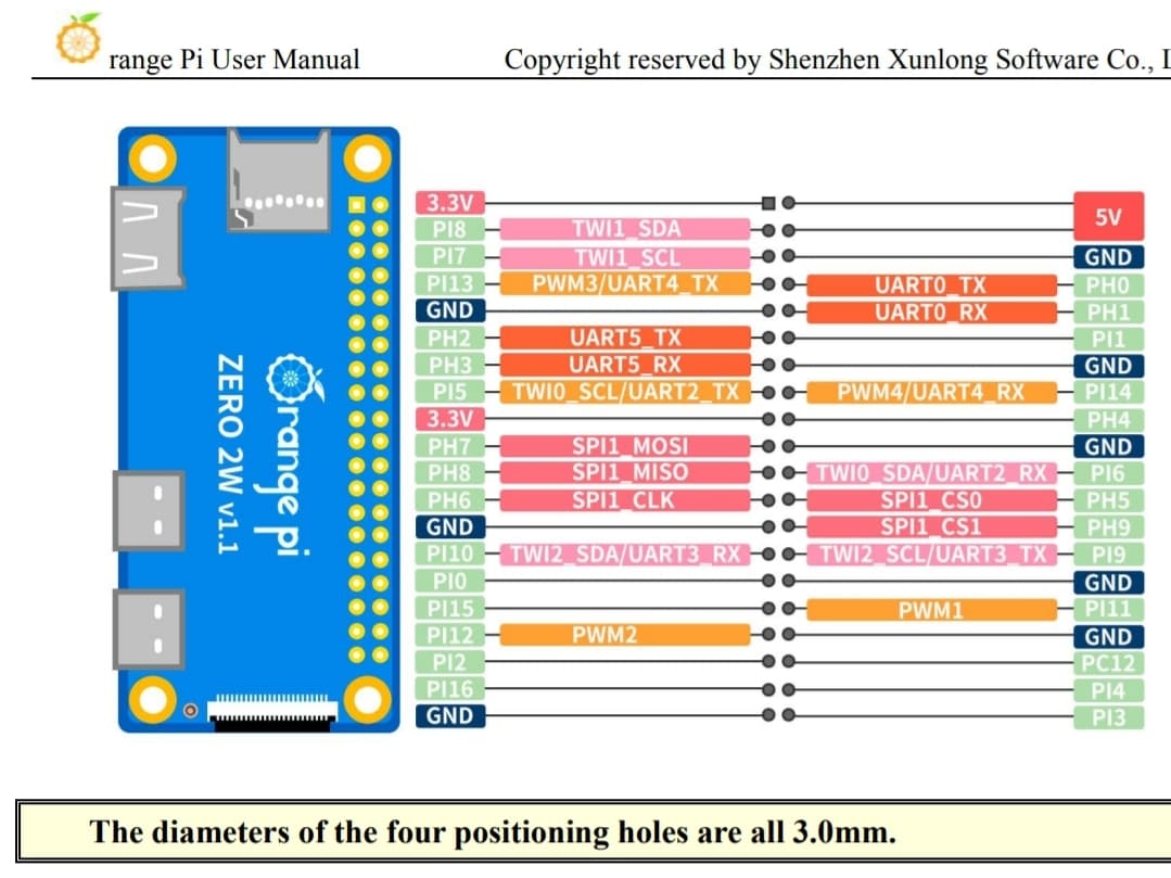
Host / SBC Orange Pi Zero 2w
klippy.log
klippy.txt (37.6 KB)

Fill out above information and in all cases attach your klippy.log file (use zip to compress it, if too big). Pasting your printer.cfg is not needed
Be sure to check our “Knowledge Base” Category first. Most relevant items, e.g. error messages, are covered there

Describe your issue:

Hello.

I had a little electrical incident with the hotend, now I don’t get any communication through UART.

can you please tell me where is the problem?

Electrical issue can’t affect just the pi leaving printer board fine can it ?

Maybe you could explain what your “little electrical incident” was we could help understand “where is the problem?”

ok, so I bought this spider hotend with the ceramic heater, it was claimed to be 400mm/s.

after installing everything, first and last thing I did was PID calibration, first run did not complete, redoing calibration no heating whatsoever only thermostat is active, then it drops an error saying test did not complete.

Switching off everything, confirming the hotend is dead by multimeter, switching back on with the old hotend, no communication with MCU.

but doing command

gpio serial /dev/ttyAS3

does show the UART is alive, don’t know what’s going on, out of panic I bought a new same printer board thinking it was damaged, but same results.

Your log seems strange:

[mcu]
serial = /dev/ttyAS3

[virtual_sdcard]
path = /home/orangepi/printer_data/gcodes
on_error_gcode = CANCEL_PRINT

[printer]
kinematics = none
max_velocity = 1000
max_accel = 1000

Is this your config? What is it supposed to do?
Where does the /dev/ttyAS3 come from? Never seen a serial device that maps /dev/ttyASn

In general, your board is simply not responding to the connection request. So, either:

  • Dead
  • Wiring issue
  • Wrong serial path. You seem to be switching between AS3 and AS5
  • Wrong settings on the host side

Since all are connected, of course a power peak can kill something on both sides.

1 Like

This one because I did many OS flashing so I was tired to refil but the mcu, until I get a sign of life

not sure, but update could’ve happened at the same time as this incident occurred.

Happened before.

For the ttyAS5 is the one port was connected during the incident, printer.cfg was assigned to it.

So I decided to test ttyAS3, same results.

It cannot affect ALL the UARTs at least, can it ?

ps: Debian distro bullseye and bookworm back and forth.

How have you wired in your Orange Pi Zero 2W?

The various UARTs to show up at different pins, but are you connecting to them?

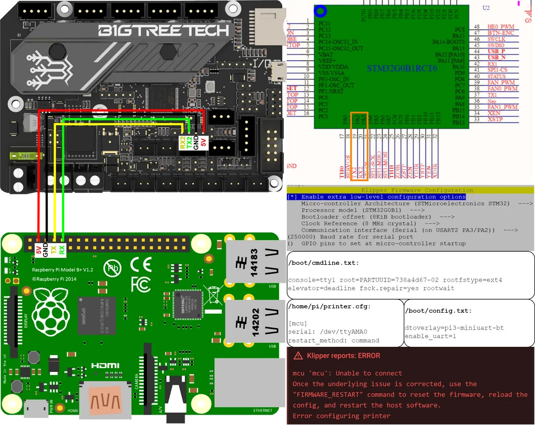
Normally people connect the UART0 pins, along with 5V and GND (so the host can be powered by the main board) when using a device with the Raspberry Pi 40 pin connector.

I’m wondering why you are fooling around with UART3 & UART5.

First time dealing with pi in general, and manual mentioned not to connect to UART0

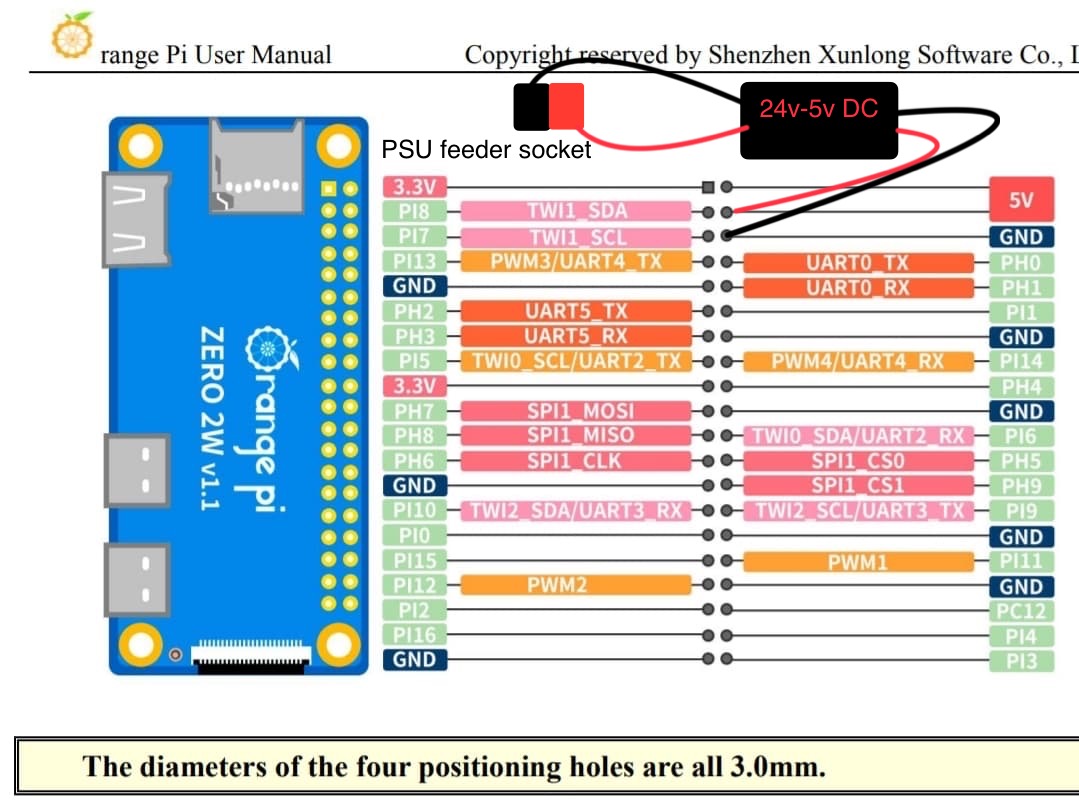
5v and GND to 24v-5v converter connected to PSU socket, UART5 to USART2 on printer board and I was connecting one accelerometer to SPI0 on the Pi and the other on printers board.

All was promising and active until that scam hotend

Okay, going back through the thread, a couple of questions:

  1. What manual are you referring to in your previous post?
  2. How do you know the BTT SKR Mini E3 V3 is still working? When you apply power to the BTT SKR Mini E3 V3, does an LED come on and if it does, where is it located?

There are two LEDs on the board, one for power and one for MCU “status” which can be handy for debugging in situations like this.

This is the traditional way to wire a BTT SKR Mini E3 V3 to a rPi 40 pin connector (note that the power from the BTT SKR Mini E3 V3 is being used to power the rPi):

Can I ask what your wiring for your Orange Pi Zero 2W and BTT SKR Mini E3 V3 along with the 24V/5V DC/DC looks like? Ideally a drawing and photograph.

Manual

The board does work, but I took extreme measurement and bought another, same situation.

There is a small detail i forgot to mention, maybe it explains why I’m getting /dev/ttyS* on bullseye.

There was this very tiny capacitor related to the SPI memory “data smoother” came off, lost and could not solder it back.

This was before the incident

Going to try something later, hopefully it works.

Reflash OS, no apt update, install klipper.

Just for confirmation that’s it’s not a bug, Debian bugs are usual.

Yep, Pi UART seems dead.
Even tried ttyS0.
it is strange how can faulty hotend damage all UART pins.
I’m still trapped in denial stage. :smiling_face_with_tear:

Sorry - at least it’s cheap to replace.

Do you have a way of programming the BTT SKR Mini E3 V3? If the Orange Pi Zero 2W was killed, I would suspect that it would be damaged as well.

1 Like

programming EEPROM? I don’t have the right tools atm :sweat_smile:

strangely it does not seem to be damaged, but as for precaution, i did not return the new board, well since i got a good deal on.

Just small question.

Will this prevent further voltage spikes?
or am I getting it wrong?

Programming the flash - Creating a new SD Card with the Klipper firmware on it.

What I would do to check to see if it still works is that I’d build the firmware with the “STATUS” LED (PD8) pin set high to see if the LED turns on and then build it without specifying PD8 high to see if it turns off.

The easiest way to check is if you had a Raspberry Pi or something similar to it.

If something has happened that could damage the IO pins on the Orange Pi Zero 2W, then it’s probably a safe bet the STM32G0B1 on the BTT SKR Mini E3 V3 is damaged as well. The STM32 IO pins are not as powerful or as well protected as those of other MCU manufacturers.

Sorry for the potentially bad news.

1 Like

it’s alright, I was ready for it, not emotionally though :smiling_face_with_tear:

I will definitely do some tests with it, jumping to klipper opened a new world to me.

1 Like

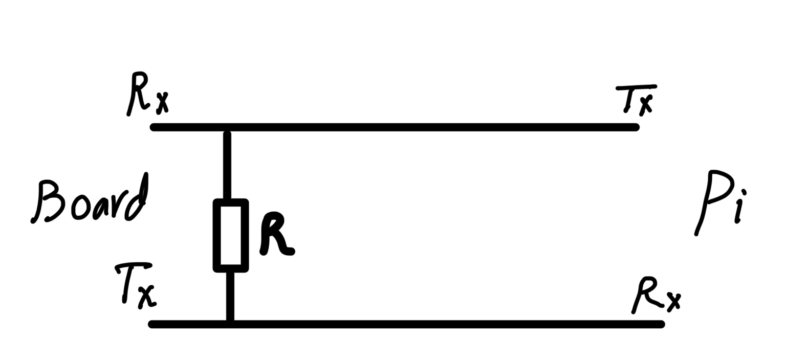
The problem was most likely something other than noise if things stopped working during the PID. A simple resistor would not have prevented this problem.

We’ll talk about wiring when you get the replacement board.

Sorry, I forgot to reply to this.

1 Like

Reading more, I think my problem was not connecting ground between board and Pi

even though it’s not feeding through 5v on board “which is wrong I think” GND between pi and board UART was a must for common ground.

Maybe I’m mistaken.

Live and learn I guess.

That’s correct - you must have a common ground for all the components you’re connecting together.

2 Likes

This topic was automatically closed 30 days after the last reply. New replies are no longer allowed.