Printer Model: Ender3
MCU / Printerboard: BTT SKR mini E3 V3
Host / SBC: Orange Pi zero 2w
klippy.log: klippy.log (7.4 MB)
Fill out above information andin all cases attach yourklippy.logfile (use zip to compress it, if too big). Pasting yourprinter.cfgis not needed Be sure to check our “Knowledge Base” Category first. Most relevant items, e.g. error messages, are covered there
Describe your issue:
…
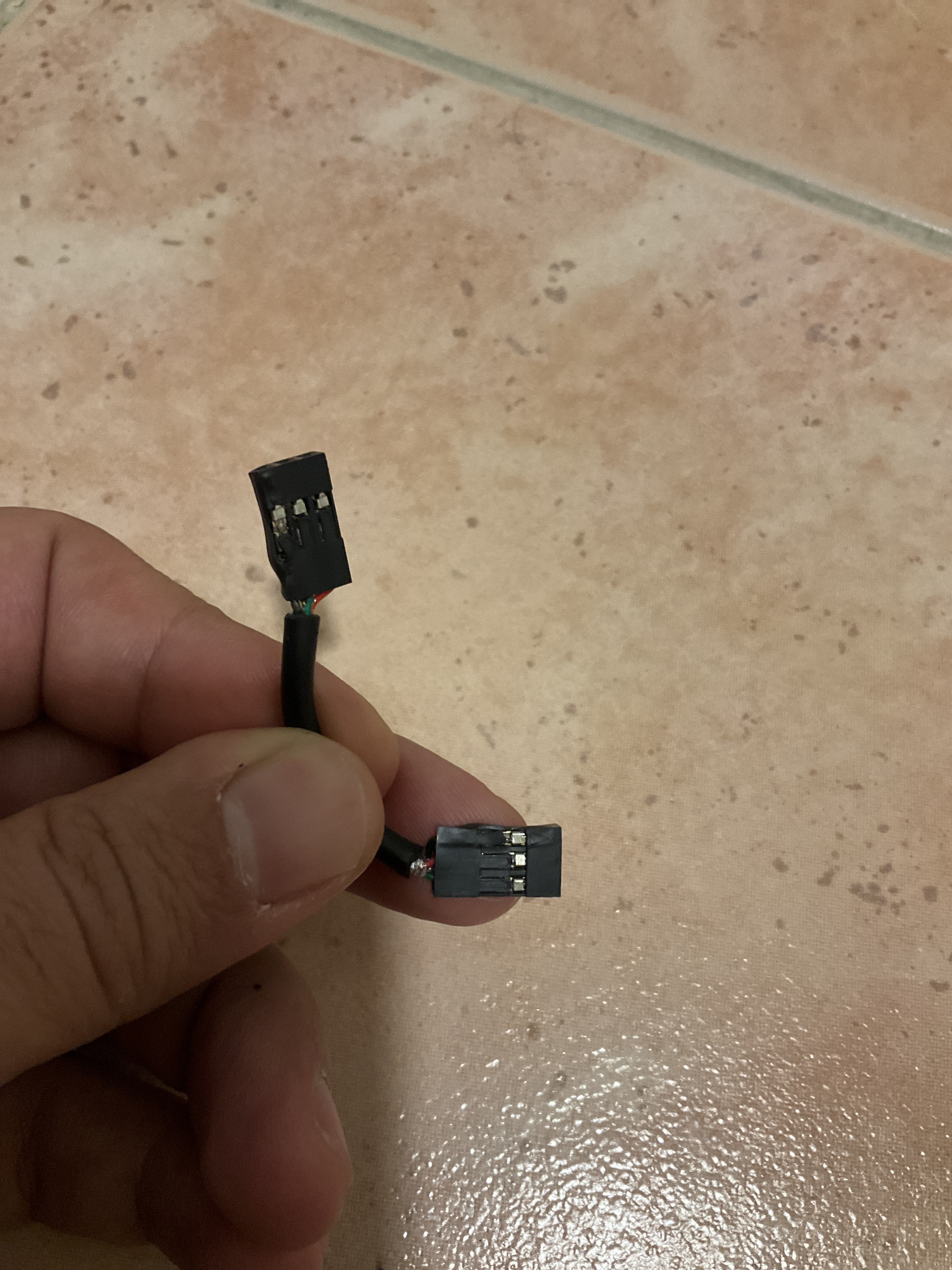
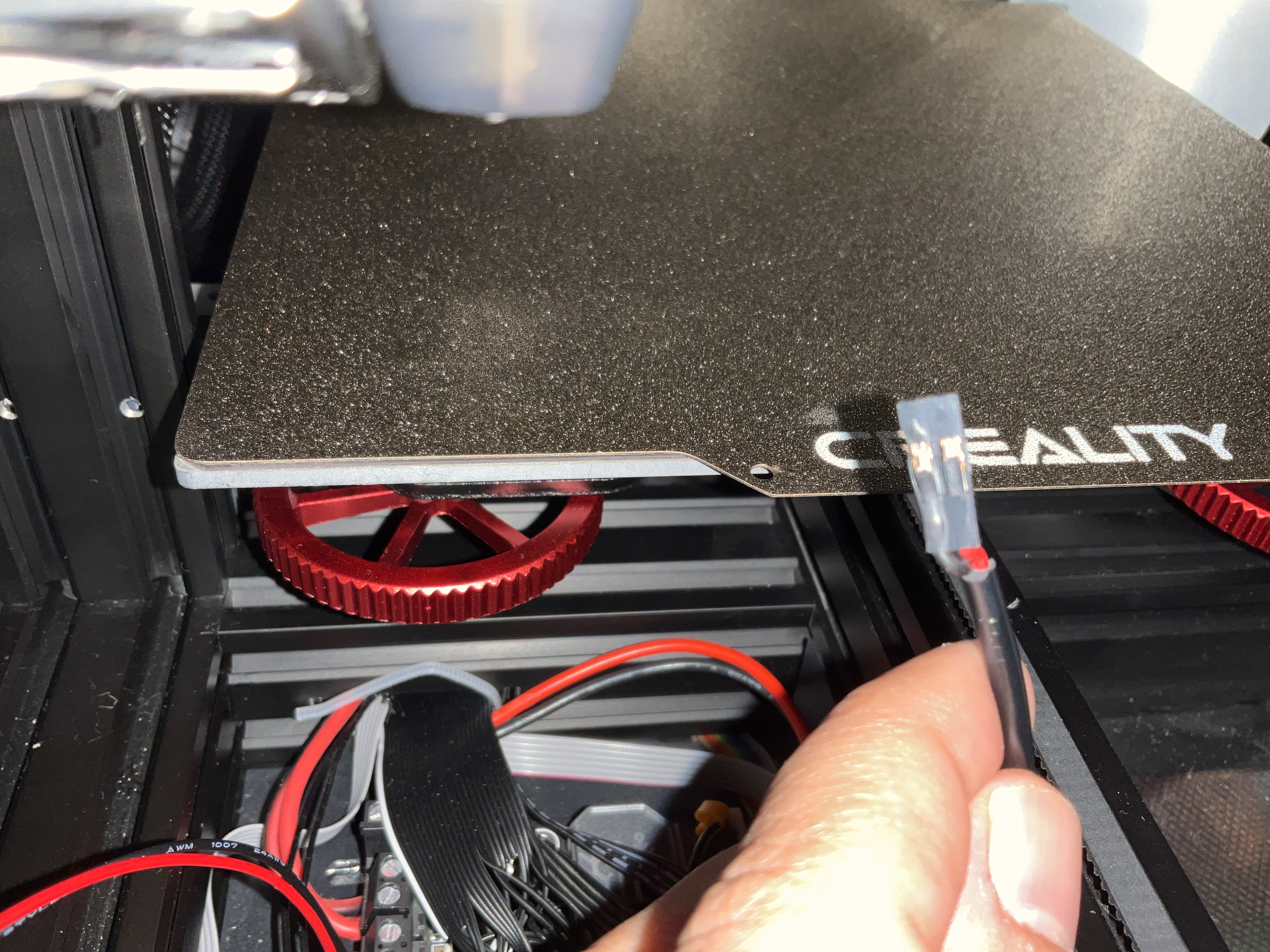
sudden disconnection this what I found while inspecting.
How are you wiring the power in your system? I’d like to see a drawing.
From your pictures, it looks like there are three connections in the cable: GND, UART TX and UART RX. Since is no power then there is current flowing through GND (and maybe the other lines) which indicates a problem with how you to powering things in your system. There shouldn’t be any current running through GND - it’s just a reference between the two circuits.
It was working fine until I sliced 3MF file on Cura, issued a print using moonraker plugin, bed temp stopped at 40C only to find that mcu went to shutdown.
I suspect that you’ve been drawing current through the GND line to the main controller board for a while. As time goes by, the wire will break down, little by little increasing in resistance until it let go.
Let’s see the TFT power and see if that’s where the problem. Otherwise, we’ll keep looking and maybe have you do some probing.
Did you connect the grounds at the power outputs of ALL your power supplies, as the Voron wiring examples show? If not, there is a ground potential forming a grounding loop through your RPi, which can destroy most electronics.
If you followed the Voron wiring then I would check the ground connections, also don’t make this mistake, the frame should be AC (earth ground) power supply input side and its metal shield, don’t connect any of the power supply output grounds to any of the frame or metal shields.
I’m only using the available UART there, connecting GND so i get a common ground, the plan was not to burn the whole UART like last time.
apparently not
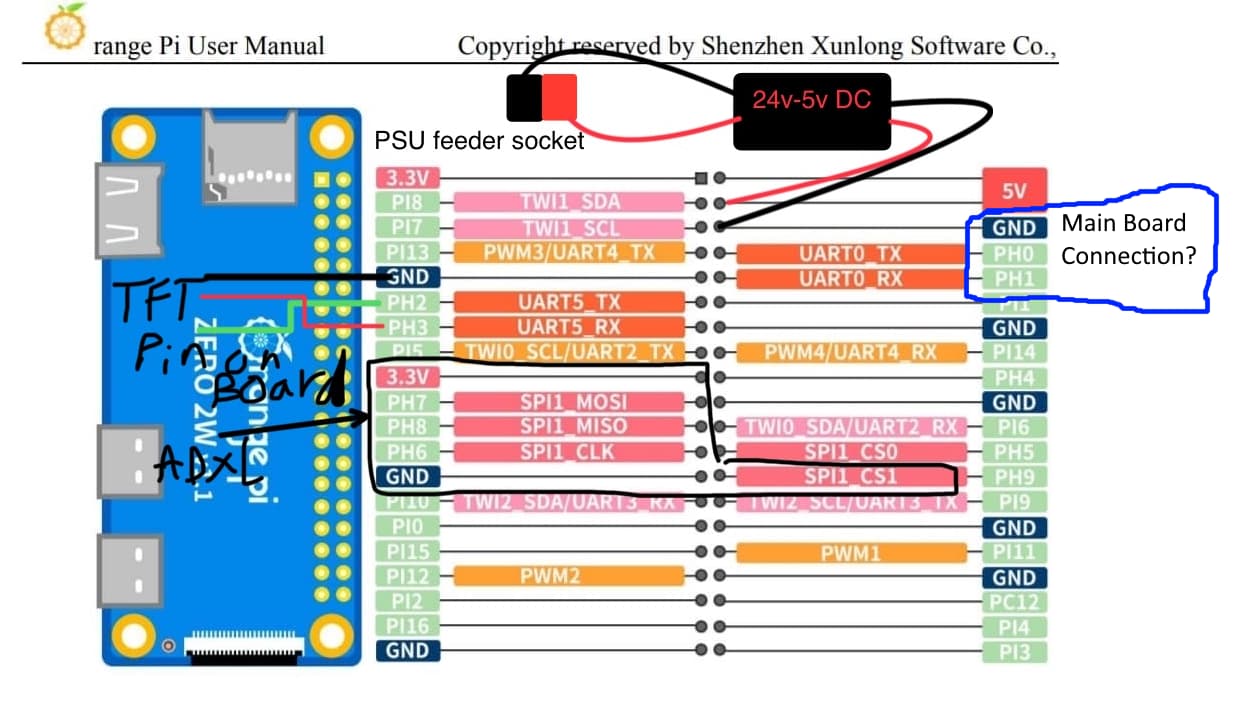
So the wiring diagram you provided above isn’t accurate?
We’re here to help, but for us to do that you have to provide accurate and complete information.
If you’re not willing to do that, then I suggest that you make up another cable between the Orange Pi Zero 2W and the main controller board knowing that it will burn out again (and, hopefully, taken nothing else with it).
No, most assume the Ground on each power supply is 0V when the grounds are not connected to the power supplies; when not commonly grounded, there will be a difference; this differential in voltage will cause a current flow if grounded elsewhere in your setup (ground loop).
Common grounding at the power supply output keeps it at the power supplies.
Let’s say you have the RPi hard grounded to the 24V power supply and connected to your 5V power supply with its +5V and ground. The potential between the grounds is 1V. The 5V PS is rated at 3A, and the 24V is rated at 15A. Depending on the current direction between the grounds, it could be 3A or 15A, though an RPi power ground wire and board traces for 3A.
I smell smoke.
The common ground wire between the power supply outputs should be the gauge for the highest amp power supply.
Nobody can answer any of your questions without a wiring diagram.
If I came across snarky in my last post (and this one), I apologize. It’s clear you have very little electrical knowledge and we’re not here to judge or mock you.
However, nobody can tell you a) what exactly went wrong b) what will happen if you wire things the same way again or c) how to fix the original problem without an accurate understanding of how things are wired.
Please spend five minutes with a piece of paper and a pen, draw your connections, take a picture of it with your phone and we can give you good answer quickly. Be as accurate as you can.
Chances are your problem(s) will become obvious when we see how things are wired.
The situation suddenly happened while I was very busy, but I chose to post the issue while I can. Even though I could not satisfy your request to the best for lacking time and materials yesterday.
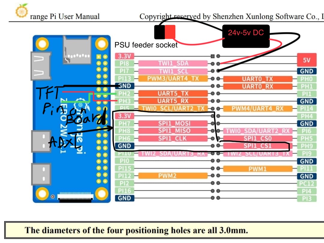
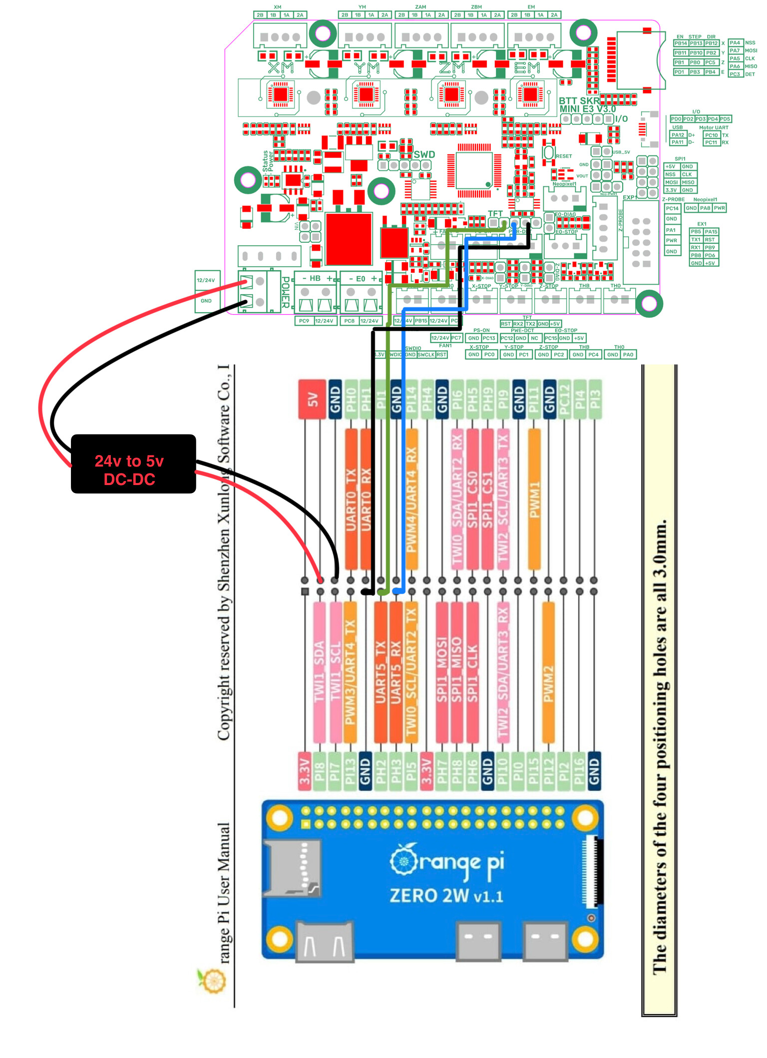
This is how things are connected.
The spi are connected to the adxl345 even though there is no power, so I assume it’s irrelevant.
But for reference the connected pins to adxl345 are: