What is the resistance when you touch the two DMM leads together?
How are you powering the ADXL?
What is the resistance when you touch the two DMM leads together?
How are you powering the ADXL?
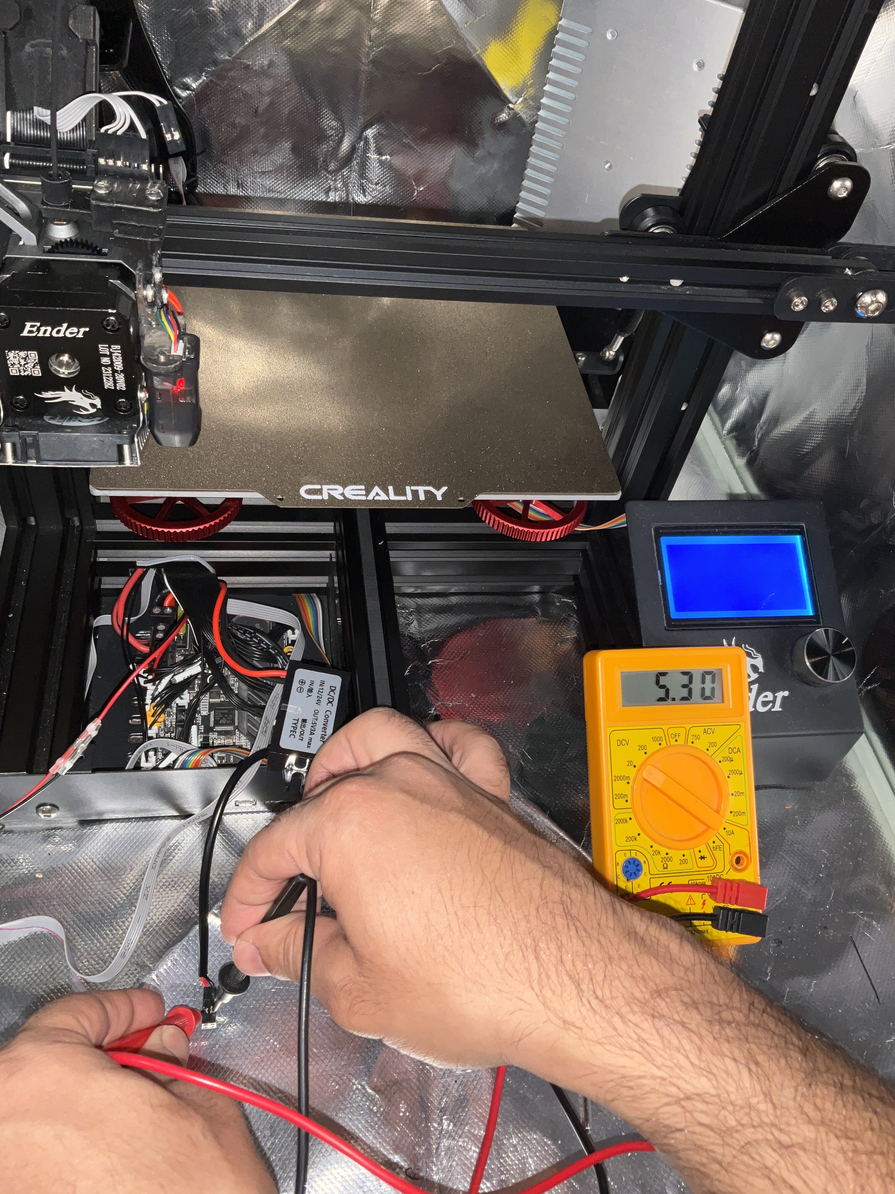
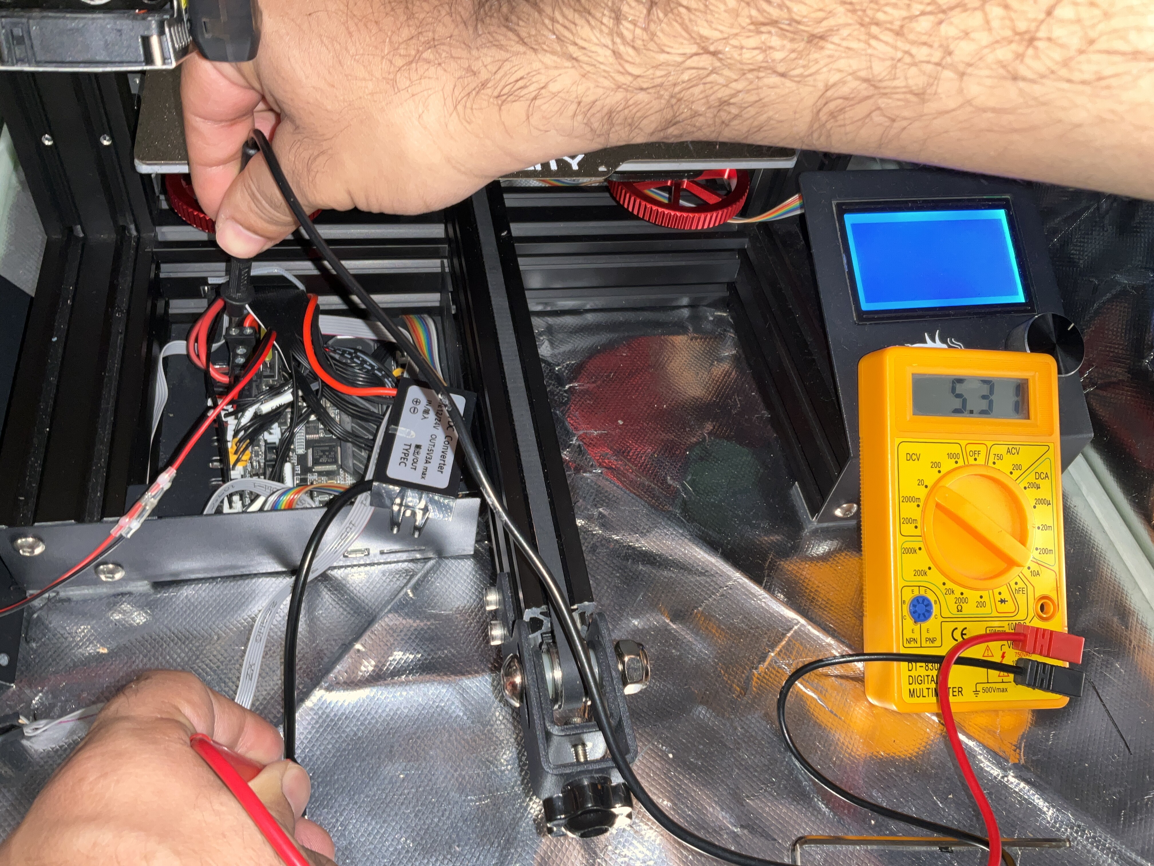
Can you disconnect the 5V DC/DC but leave it connected to the 24V supply and measure the voltage, relative to ground of the main controller board, of “V+” and “V-” of the 5V DC/DC?
What are you trying to show here?
Yes, that seems to be ok. Just to clarify, the DCDC wasn´t connected (in- and output) while measuring?
Another possibility might be, your mcu isn´t connected to GND properly; if so, the mcu will use GND via your Pi and the UART-GND.
So please doublecheck GND on your MCU.
will do when i get back home.
i just compared two klippy.log files, one belong to my previous Pi “dead UART” klippy.txt with the one mentioned in this post.
this line
mcu ‘mcu’: got {‘offset’: 0, ‘count’: 40, ‘#name’: ‘identify’, ‘#sent_time’: 0.0, ‘#receive_time’: 254.571613204}
was almost continuous in the previous log file.
I’m Just banging my head out of frustration, but as strange as it be hopefully the pi is fine, or it’ll cost me another month+ of waiting for new one.
What is “it”?
Can I ask you to be as clear and explicit as possible? Even if you think you are repeating yourself it would be helpful for us to understand exactly what you are talking about.
Those cracks in the compound are no clear indication of something bad going on. It seems to just be some stress on the cabeling entering the compound.
When all cables where attached while measuring, you won´t be able to measure the internal connection between the Input and Output GND. At least the Pi-Side has to be disconnected in order to measure the internal resistance. There are some DC/DC with galvanic isolation; the measurement is to see if this is the case on your DC/DC.
Did you measure the Output-Voltage of the DC/DC to GND of your MCU as @mykepredko mentioned?
Please recheck all GND-Wires if they are connected properly, espacially the GND from the PSU to the mcu.
Horribly mixed up two things, plus bad English, apologies.
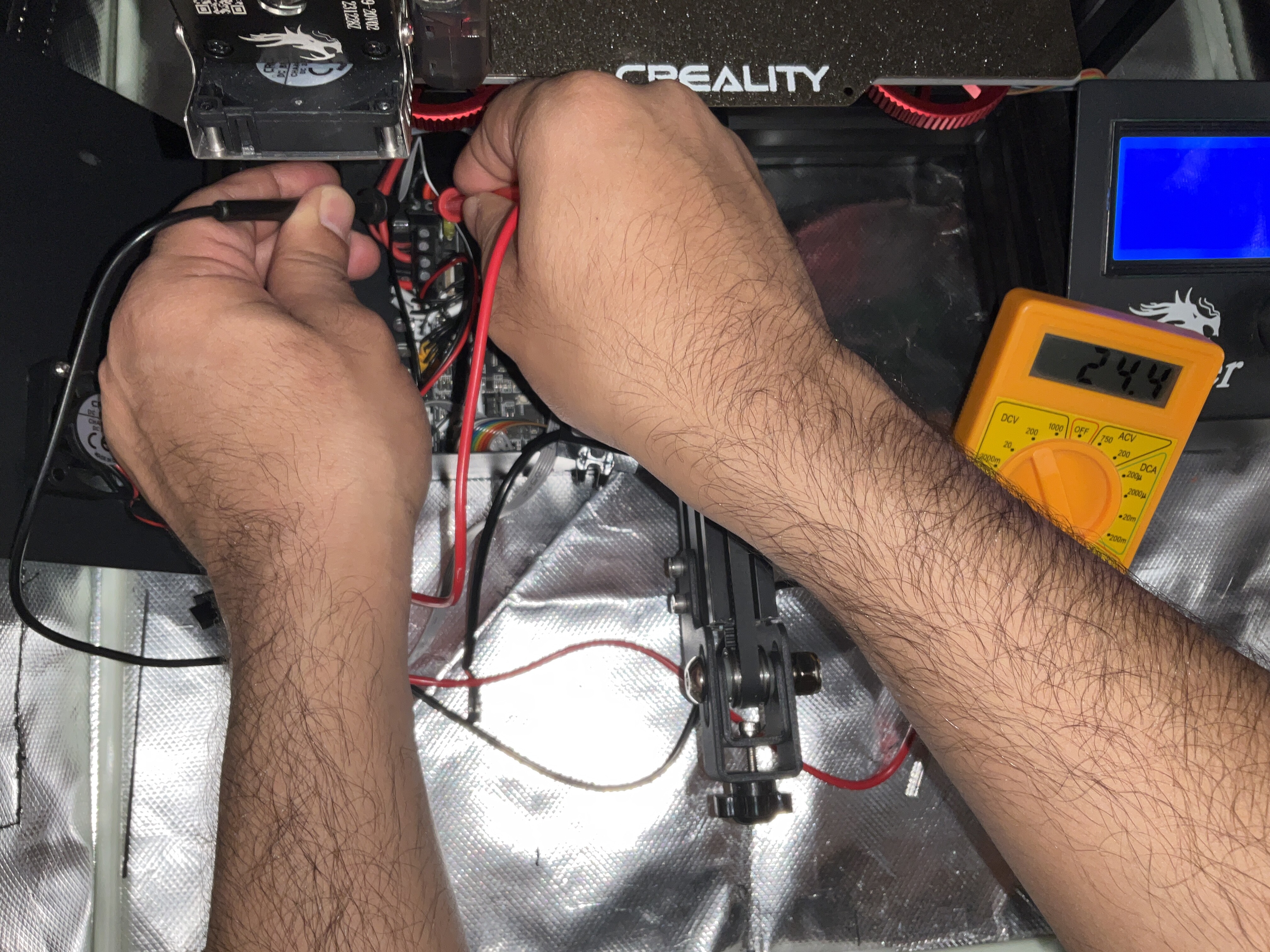
Like this ?
Rechecked the GND wires, all tightened.
The issue started while bed was heating.
Could it be the bed went bad?
NO!!!
You are measuring the output of the 5V DC/DC relative to its Ground not relative to the Ground of the main controller.
You should have your Red lead on the output of the 5V DC/DC and the Black Lead on the Black wire going into your main controller board (I believe that is where you are getting the input power to your 5V DC/DC.
As a secondary point; that 5.30V shown on your Voltmeter is concerning. The Orange Pi Zero 2W is a very low end device built the cheapest parts possible to do the job.
The ETA3409 (I went through the Orange Pi zero 2W’s schematic) used to drop the (nominal) 5V input to 3.3V used in the device is really marginal for this application.
If possible, I recommend that you dial down the output of the 5V DC/DC or replace it with another that outputs something closer to 5V.
I think I should just do what others did, taking power from 5v pin on the MCU.
Edit: since the amps on the board are lower than required for pi to work “1A”, you just add 2x 5v pins, that should double the amps.
It could work right?
You should be able to get 2A from a single pin on the main controller board - I do that all the time.
Can you measure the voltage between the main controller Ground and the 5V DC/DC Output Ground?
i did, it’s 0v, couldn’t take pictures though.
Im going to flash marlin, to confirm whether MCU uart is damaged or not.
the LCD screen shouldn’t work properly if uart pin is damaged right ?
What is this LCD? When asked about the “TFT” you replied:
Again, you need to be absolutely clear on the printer configuration and how it is wired. This is post 34 of this thread, it’s gone on about three times longer than I would have expected and it’s due to you not being accurate, clear and consistent about the printer’s configuration and wiring.
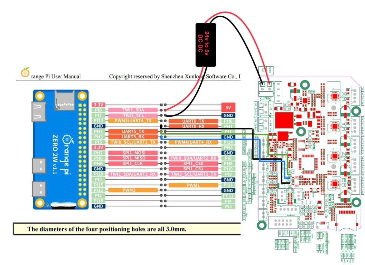
You have put in two incomplete wiring diagrams and I am assuming that the second one:
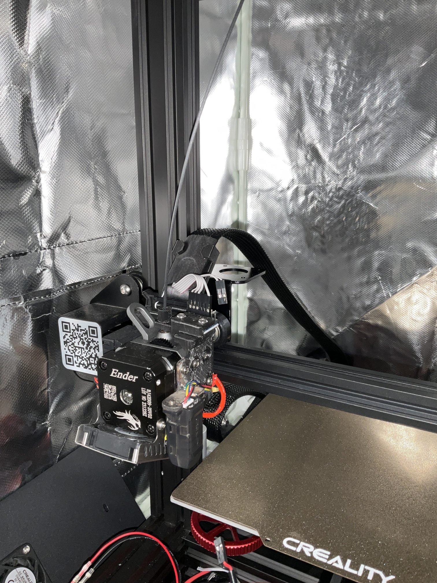
Is correct. There is no LCD or TFT. There is no ADXL.
If this drawing is not correct, then you need to clarify things now and provide information that is absolutely correct.
To test the MCU in the BTT SKR mini E3 V3, could I suggest that you reload Klipper with the STATUS LED (PD8) specified in make menuconfig. Now, when you apply power the the board, the LED attached to the MCU will turn on - if this happens, then there is a very good chance the rest of the MCU is fine.
Once we’ve done that, I’m going to guide you through wiring the Orange Pi Zero 2W without the DC/DC power supply.
We can do this either using UART cables like before but I would prefer to do it with a USB C to USB Micro cable (if you don’t have one, please see if you can get one). That will be less work for you and a faster, more reliable connection.
In either case, you will have to wire up a jumper that will bring power from the BTT SKR mini E3 V3 to the Orange Pi zero 2W.
stock LCD, EX1 pin have UART1, which appears to be working.
I did mention the modifications added to the printer in this post, meaning everything else should be stock.
I was going for the look using UART, now it’s dead for the second time, will be using USB.
Please do a diagram
Before we can go forward, you need to provide a single, accurate electrical drawing of your system. In that, all the peripherals connected to both the main controller board as well as the Orange Pi zero 2W need to be included.
I asked for this as the second reply to this thread and you have provided conflicting information on what is in the system, how it is wired as well as two, incomplete, wiring diagrams which show different connections and peripherals.
Without wanting to add insult to injury, I think its time somebody asks what is the level of knowledge, expertise or background education of the original poster in this field of electronics, troubleshooting and wiring diagrams?
From my distant point of view I get the distinct feeling that there is no basic knowledge present with regards to electrical schematics and trouble shooting, and if this is the case you could create a false security which in turn could result in a disastrous situation. A house-fire is not unthinkable imho.
I am not saying this will happen, or that I am 100% right! I just would like to point out my observation plus the fact that I have learnt from decades of trouble shooting in the field, that when asked questions like this which are not in somebodies field of expertise, the answers often are mixed with their own thoughts and expectations. This makes the process of concluding what is going on from a distance really difficult.
I would also like to point out that I do not believe there is unwillingness or malice at play, it could simply be a result of inexperience.
Keep safe everybody!
Truly sorry for the havoc I created here.
Due to some circumstances I have, living in a remote area, really time consuming for technical repairs ‘unavailable’, purchasing new tools/devices and adding that this is the second time for this incident.
I had a little breakdown looking for answers I wanted.
This was the right answer, after looking in the schematic
OPi_ZERO 2W_SCH.pdf (566.0 KB)
and from this line
It looks like TX isn’t TXing, but RX is receiving.
maybe due to power being kind of unavailable.
my guess is that voltage caused VCC-IO burnt in both boards, I will make time to inspect for marks and hopefully finding a technician with the right tools to do the job, hopefully it’s something repairable.
Also there must be a potentiometer in the printer PSU, hopefully is easily located to bring voltage down to acceptable limits, thus bringing down that 5.3v in converter to acceptable limits.
FYI I’m electrical engineer ![]()
but being in a job far from my field and short of time and tools for practicing, took a heavy toll on me.
I have a degree in electronics engineering.
I have worked for many years for an electronics contract manufacturer in Huntsville, Alabama.
Self-employed for many years as a software programmer and repairing Personal Computers.
I have been using and building 3D printers for over 8 years.
I have found many board design errors on BTT products, including the GTR, M5, and Octopus boards. I created schematics for the GTR and M5 well before their official release.
I didn’t mean to question anybodies credentials really, certainly not of the people who offer help here.
Its just that the thread seem to me to move out of control with questions and actions moving further apart at every step.
For this reason I asked to see if everybody involved was aware of what was going on, that was all.
From your (@NAPCAL ), and Mykepredko’s (@mykepredko ) questions and reactions I know you two know what you are talking about. I did not feel the same from the original poster.
I think this was a case of combined language and not being prepared with all the correct info, which can lead to huge misunderstandings.
Anyway I am pleased it has been resolved.