Voron 2.4 CanBus: Lost Communication to mcu (EBB36)

Basic Information:
Printer Model: Voron 2.4 350
MCU / Printerboard: BTT Octopus
Host / SBC: Raspberry Pi 4B
klippy.log

Hello everyone,

I’ve been having issues with my Voron 2.4 for a while now. It keeps losing connection to my toolhead board (EBB36), which runs over CAN bus. Currently, the print fails after a maximum of 10 minutes. However, I was recently able to complete a 2-hour print.
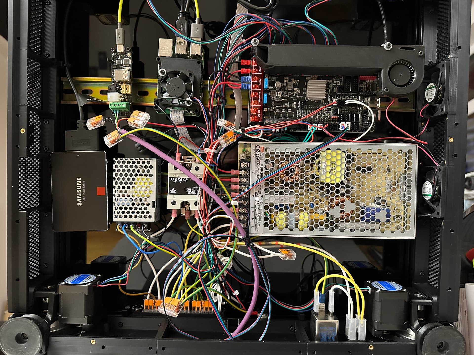
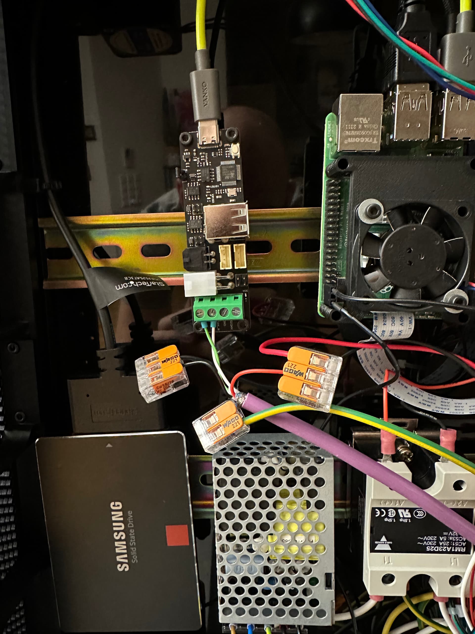
Setup:

Voron 2.4 350
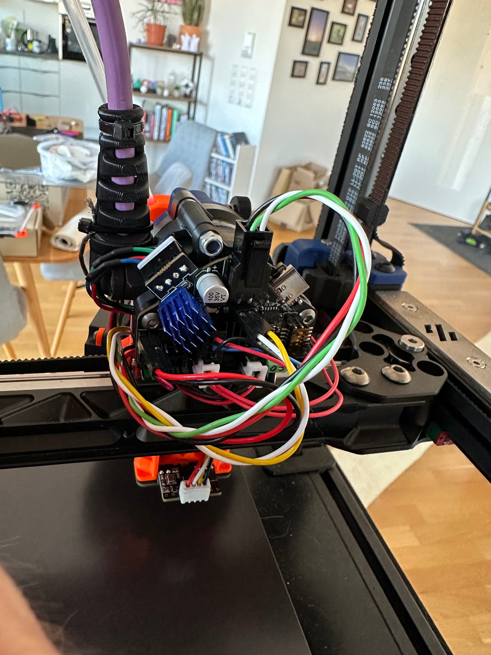
BTT Octopus → Raspberry Pi 4B → EBB U2C → EBB36 → Cartographer3D
Extruder stepper is connected via the EBB36
CAN cable: Igus Chainflex CFBUS.066 with shielding grounded
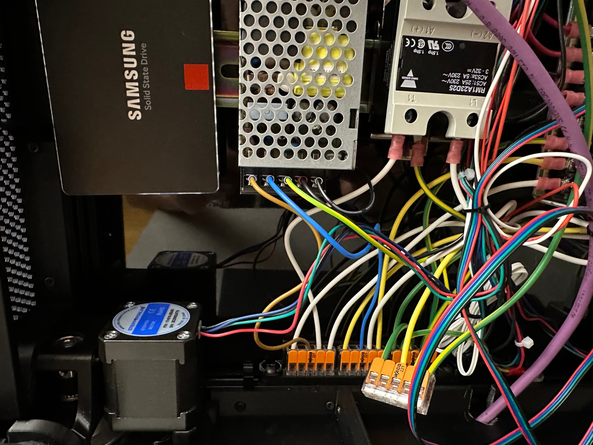
One Meanwell PSU for 5V (for the Pi) and one for 24V
Graphite Bed with 750W AC Heater (grounded as well)

What I’ve already tried:

  • New U2C
  • New EBB36 toolhead board
  • New umbilical cable
  • New USB cables
  • Grounding the extruder stepper
  • Printing without heated Bed

The only thing I haven’t replaced yet is the Cartographer. But according to the Klippy log, the printer loses connection to the EBB36. Just before the disconnect, the retransmits to the EBB36 increase significantly.

As seen in the Klippy log, the bandwidth is often at 100%. I unfortunately can’t figure out why.

My CAN bus configuration follows the Esoterical CAN bus guide:

  • Baud rate: 1M
  • txqueuelen: 128

At this point, I’m starting to doubt it’s a hardware issue. Possibly something else?

What I still want to test:

  • Lowering the baud rate to 500k (according to research, 1M is more prone to interference)
  • Replacing the Cartographer3D
  • EMC (bed, heater, …)
  • Firmware versions

Attached are some Klippy logs and my configuration.

Any ideas are welcome. I’m running out of options and seriously considering ditching CAN bus…

Best regards,
Andreas

printer.cfg (25.0 KB)
canbus.cfg (2.4 KB)
Unfortunatly i can only add 2 attachments… I will ad the Klippy logs later

and here are the latest two klippy logs:
klippy(14).log (1.6 MB)
klippy(13).log (1.7 MB)

Try to either connect EBB to the octopus or flash the U2C with the klipper and define it as an MCU.
Right now, there is no data on how/where it loses communication.

That is it.
I assume that the EBB is in the middle between the U2C and the Cartographer, and both the Cartographer and the U2C have termination resistors installed.

If so, there is no issue with U2C to the CAN connection, but most probably with the CAN to the EBB connection, that is it.
Simply bad contact or some sort of EBB power issue.

You can take a look here, maybe it is releated: New Voron instance lost communication with EBB (can bus)

Thanks for the quick reply.
The Jumper for the 120Ohm on the EBB36 is not connected. The Cartographer has a bulílt in 120Ohm restistor. The can termination on the U2C is set.

Unfortunatly i have no capacitor here to try the solution in your link.

Three questions:

  1. Could you provide a wiring diagram for your printer? I’m particularly interested in how you are distributing power and ground. This also includes the Raspberry Pi and its power supply. Let’s make sure you don’t have any ground loops or voltage shifts.

  2. Have you considered dropping the EBB U2C and using the CAN interface on the Octopus? Doing that cuts down on wiring (and opportunities for problems there) and complexity at the bottom of the printer. It also simplifies the set up procedure.

  3. What is the process you used for setting up your printer. I always recommend the Esoterical CAN Bus Guide.

It seems that the extruder heater is defective, because the printer has been running for over an hour now without any errors with deactivated extruder heater.
I have a spare heating cartridge for my Revo-Hotend. I’ll replace it and see if it’s better afterwards.

Can a defective heater cable cause voltage peaks that interfere with the Canbus signal or cause the EBB36 to crash?

@mykepredko

  1. I have followed Voron’s instructions exactly. In addition, I only connected the sheath of the CAN bus cable to earth.
  2. I could also test that. I think I read somewhere that it should be more stable with the U2C.
    Regarding
  3. I set everything up exactly according to the “Esoterical Can Bus Guide”.

Yes. Spikes on the power line can cause problems with the EBB36’s MCU power supply.

Not in my experience - I’ve found that having CAN on the main controller board and running the Klipper in CAN bridge mode is absolutely solid.

There’s also the (very big) advantage of simpler wiring of using the CAN built into the Octopus.

I swapped the heater and the next print failed as well… :sob:

To switch to Can bridge, i only need a RJ11/12 Cable, wire the toolhead directly to it and flash the Octopus right?

I just meassured the 24V PSU. Its 24.25V idle. Should I increase it a little bit? Maybe it drops under load?

EDIT: 24.22V when its printing.

Sorry.

Just to be clear - with the heater off, things run okay for an hour but if you activate the heater it crashes after a few minutes?

I suggest that you hold off on any changes to the CAN U2C/Connections until we get this figured out.

What is your 24V PSU? What is the make and model number?

Again, I’d like to know how you’ve wired the printer. Could you provide a diagram and include your wire sizes?

In the OP, you said you’ve “been having issues with my Voron 2.4 for a while now”. What exactly does that mean? Did you make any changes to the hardware or firmware that may have precipitated these issues?

You are right. Without heater, 1h print. With heater 1-5min until it stops.
The 24V PSU is a meanwell RSP-200-24.
I’ll post a drawing of the wiring tomorrow.
Here are some pictures of the wiring:


The Can umbilical is AWG20 for the 24V. This could be a bit small right?

I have problems with the can bus only. No other problems.
I changed quite a lot in the last few weeks. I swapped my Aluminium bed plate against a graphite one, changed from XOL with G2E and revo voron (also with EBB36) to a self designed extruder with G2E and EBB36. Problem is, I’m not really sure when the problem started. I think it started after I swapped to the own extruder. But I haven’t changed any electrical hardware…

Some things here to work with:

  1. “The 24V PSU is a meanwell RSP-200-24”
    – That’s going to a bit tight to provide enough power for your system - That bulk supply will provide a maximum of 8.3A.
    – I presume you have your steppers set to around 0.8A each (that’s what I have), so when X/Y are moving you’re drawing the full amount and probably around 0.5A or so for your Z axis steppers when they’re idling/keeping position, you’re probably drawing 0.5A for your extruder - that’s 4.1A right there. You’ve got a number of fans and they probably take at least 1A. Then there is the Octopus, U2C and EBB36, together they’re around 0.8A. I presume you have at least a 40W heater on your extruder - that’s another 1.7A when active. The big difference between what I spec’d out above and my system is that I run with a 50W heater (which would add another 0.4A).
    – This works out to around 7.6A and I don’t know if you have anything like extensive LEDs or a TFT display running (it looks like you have display attached to your rPi). You don’t have a lot of current margin here - less than 10% of the rated output with what I’ve listed here.
    – Personally, I run with a Mean Well LRS-350-24.

  2. What is the “Samsung Solid State Drive” doing in there?

  3. The changes you’ve outlined shouldn’t have resulted in any issues.

From what you’ve outlined here, I would recommend getting a heftier bulk power supply.

Taking a quick Google search, it seems that a 200W 24V power supply is what is recommended for the Voron 2.4 but that seems light to me.

I can’t remember what the power supply that was supplied with my Fysetc Voron 2.4 kit but I’m running with the LRS-350-24 now. I don’t remember every replacing it so I guess that’s what came with it but I can’t say for certain. I can say I’ve never had power issues.

This interesting approximation, but it is most probably not correct.
What if there are 2.5A motors? (Like LDO 2504 as example)

They would in total consume around half of the available power at peak:
~25W per XY, 10W per Z, 25 * 2 + 10 * 4 = 90W
(if they are running at rated current)
You can validate my numbers yourself with the multimeter and measure the actual current draw at different modes. FORCE_MOVE would allow for moving only one motor, which could be handy.
Or you can simply measure the base current (motor disabled), and current after the motor has been enabled (hold). When Z is moving/probing. When XY moves.

Like, yes, it is close to the sun, but only in very specific circumstances.

Also, if PSU were overloaded, it would lead to the whole system shutting down.

AWG20 ~ 0.5mm^2, it should happily handle the 5A load. It is possible to do the thermal calculations and voltage drop, but I doubt it is necessary, taking into account the small length and that most of the time, nothing on the toolhead consumes 100W.

You can, I doubt that it would help a lot, but you can.
Alongside, you can play with increasing of the PWM frequency of the heater to spread out load:

[extruder]
....
pwm_cycle_time: 0.002 # 500Hz

You can also try to decrease the peak power with the max_power: 0.75.

The thing is, Revo HeaterCore is a PTC heater, it has a power curve that depends on the actual heater temperature.
It is possible that it can draw 100W when cold (there is no info).
It is possible that under the current default configuration, it does lose some temperature in the 100ms time window (default cycle time), and then draws more current until it reaches the target temperature.
Which could lead to some power spikes, which in the end could be a root cause here.
This is a hypothetical scenario.

Then the voltage decrease would decrease the peak current. But would also decrease the amount of energy stored in the capacitors. With the increased voltage, vice versa.
Increased frequency could spread out the effect of the PTC, which could help, or could not.

Hope that clarifies things a little.

Where do these numbers come from? I don’t see how they’re derived from the previous paragraph.

How do you propose to measure the currents with a multimeter?

It is very difficult to measure motor currents and peak values without equipment that is meant for the task.


You just put in:

That is literally the point I was making.

1 Like

AFAIK, most multimeters would be able to measure up to 10A of current.
You can put it between the PSU and the motherboard.
In the case of the octopus, above, it is even easier, because there is a separate power line for the motors from the PSU.

We do not care how much the motors actually consume. We do care, how much power is used from the PSU. It is possible to measure the PSU voltage, we can use the highest, without load.
Then measure the current, which is drawn from the PSU to the motherboard/motors, and that would give us some numbers which would be close to the actual load.
Then simple math V * A = W

My small tests on CoreXY with a separate 48v 70W PSU for the XY:

Some public data for some XY motors on voron at different speeds/currents: https://www.youtube.com/watch?v=Zpob3VVTzp4

It is not precise in absolute terms, but should be precise enough to give an estimation:
“How much does the drivers + motors consume the power from the PSU?”

It seems to me a fairly simple/widely available solution.

I guess I should have been more specific - How do you propose to accurately measure currents on a motor?

Multi-meters are, at best, adequate for measuring steady state current. They cannot catch transients due to starts/stops and changes in loads.

Maybe I should have been more explicit but @Kridi88 does not have a lot of margin, any additional load will cause his bulk power supply to go into overcurrent protection and power will be lost.

In the video link you posted, go to 11:28 - Eddie points out that to fully quantify stepper motors an oscilloscope with current probes are required. This is the start of what I would expect - there is additional equipment, like the Trinamic TMCM-0013-#A series of probes:

https://www.analog.com/en/resources/evaluation-hardware-and-software/evaluation-boards-kits/tmcm-0013-xa.html

The use of the word “we” is incorrect here. You may not care but I do.

Over the years, I’ve found the best path to understand power draw is to have a current model that can be articulated clearly. Going back and forth and translating back to power is extra work and can be misleading.

I’m trying to put what you’re saying into engineering terms and I’m having difficulty.

For example, why are you dividing by two here?

(Incidentally, you’ve posted the same video for both cases).

Are you saying that the windings have 0.5Ω resistance? If that’s the case, then that’s the at rest power formula, not when they are turning.

However, when stepper motors are turning, they are essentially an AC motor and the formula for power in an AC motor is:

Pac = V * I * cos(φ)

Where φ is the angle between Voltage and Current. You need a two channel oscilloscope with a current probe to be able to measure the voltage across the motor terminals and find the phase angle (φ) between the voltage and current. I should also point out that “Voltage” is voltage across the motor terminals, not the 48V of your power supply - when an AC motor is turning, you get Back EMF that will result in a different voltage across the motor terminals than what you’ll probably expect when you have current drivers like the ones in the Trinamic chips.

To net out what I’m trying to say here; I don’t have any confidence in your 25 RPS power calculation.

This is why I go with the current values set by the stepper drivers, they are reasonably accurate (probably within 20%) at a macro level and do not result in misleading conclusions.


In any case, you seem to agree with me that the bulk power supply @Kridi88 is using is marginal.

I still recommend that he try one with a higher power rating, like the Mean Well LRS-250-24.

My two cents:

  • I spent hours researching the topic of supply power demand for the purpose of laying out the PSU ratings.
  • I have not found any comprehensive mathematical model describing it. Some of the better resources I came across:
  • The hands-on approach taken in the video @nefelim4ag posted and his own measurements seem to be the best way to get a ballpark estimate:
    • Measure what the PSU sees, either with a DMM or a lab bench supply as in the video
    • For the PSU phase shifts etc., do not make a difference: It delivers and displays the measurement for what is requested
    • The measurement either in the lab supply or in the DMM will likely not catch transients or peaks. It is likely more of an average power demand value, but this can be covered with a safety margin
    • Additionally, there are enough capacitors around to help smooth out such peaks
  • Given that you should anyway consider a margin of at least 30% for the PSU, a value of around 35 Watts for the average 3D printing motor seems a sound approach.
    • For a complete worst-case scenario, use P = V_\text{motor_supply} * I_\text{motor_max}, or maybe a less overrated P = V_\text{motor_supply} * I_\text{motor_RMS}. An overdimensioned PSU is the much lesser evil than an undersized one.

Sooooo, my X, Y, and Z stepper motors are all set to a run current of 1.1 A.
These are the motors I use: Klick meee
Then, I use TMC_autotune: https://github.com/andrewmcgr/klipper_tmc_autotune?tab=readme-ov-file

Now that I have a lighter toolhead, I have been able to significantly increase the speed and acceleration. Of course, this could also lead to a higher power supply requirement.
Currently, the travel speed is 500 mm/s with an acceleration of 8000 mm/s².

Unfortunately, max_power: 0.75 and pwm_cycle_time: 0.002 did not help.

I have a socket that measures the power of the entire printer. With the heated bed switched off, the printer consumes approximately 100 W, but the socket will probably average that out.
I have a 1,300 W laboratory power supply. Could I test whether it’s the power supply by plugging this in instead of the Meanwell?

I just also measured the Voltage on the Toolhead. Idle its 24.2V and with the heater on its 24.1V. Should be fine I think.

Edit: The error also occure with the laboratory PSU hooked up…:
klippy(18).log (8.3 MB)
Error message is: Heater extruder not heating at expected rate
But i think its because he is loosing connection to can0 because of bytes_retransmit=4114

EDIT2: Klipper is installed on the SSD. Its the storage for the Pi.

1 Like

Overall, this topic sounds like a classic Timeout with MCU / Lost communication with MCU with the only way out being to systematically exclude the individual points.

No surprise there - I think you’ve got a pretty good setup except for the 200W bulk power supply.

That sounds like a good plan.

When I look at your latest klippy.log, you have set the steppers at currents considerably higher than what I use so I really think that you should be looking at your power supply.

I’m looking forward to seeing how this works out!

(My bad, thanks, fixed).

This is a CoreXY machine, sure, like the Voron 2.4 in this context/topic.
To hold the position, there are 2 motors.
To move portal/toolhead along the X or Y axis, there are 2 motors.
There is a separate 48V 70W power supply to power 2 TMC5160, which drive those motors.
So, if I measure the current from the PSU to the drivers, it is always the sum of the current to each motor. Assuming both motors do an equal job in standstill or moving the portal, I can also simply assume that the RMS current (and the power) would be split equally between them.

Hope that clarifies my calculations.