X Layer Drift after instaling BLTouch

Basic Information:

Printer Model: RepRap Anet A8 based
MCU / Printerboard: Arduino Mega
klippy.log
klippy.zip (1.7 MB)

Fill out above information and in all cases attach your klippy.log file (use zip to compress it, if too big). Pasting your printer.cfg is not needed
Be sure to check our “Knowledge Base” Category first. Most relevant items, e.g. error messages, are covered there

Describe your issue:

Hi, I noticed this weird problem with my printer/setup after installing BLTouch. Basically my prints started to have some kind of layer shift or something like that.

Let’s assume that I want to print perfectly straight part, something like calibration cube, but my print actually looks more like that
image

Red line is showing how it looks in real life.
I really don’t know what might be the cause of this issue, I noticed it after installing BLTouch, but I don’t know if this is somehow connected or unusual coincidence.
This layer shift happens only in X axis. Y is perfectly straight. I checked for loose belts or loose sprockets on steppers, but they are fine.

This is my printer.cfg

[include mainsail.cfg]

# Printer Kinematics
[mcu]
serial: /dev/serial/by-id/usb-1a86_USB2.0-Serial-if00-port0

# See docs/Config_Reference.md for a description of parameters.

[stepper_x]
step_pin: PF0
dir_pin: PF1
enable_pin: !PD7
microsteps: 32
rotation_distance: 40
endstop_pin: ^PE5
#endstop_pin: ^PE4
position_endstop: 0
position_max: 214
homing_speed: 50

[stepper_y]
step_pin: PF6
dir_pin: !PF7  # Changed from !PF7 to PF7
enable_pin: !PF2
microsteps: 32
rotation_distance: 40
endstop_pin: ^PJ1
# endstop_pin: ^PJ0
position_endstop: 214
position_max: 214
homing_speed: 50

[stepper_z]
step_pin: PL3
dir_pin: PL1
enable_pin: !PK0
microsteps: 32
rotation_distance: 8
endstop_pin: probe:z_virtual_endstop
position_max: 150

[extruder]
step_pin: PA4
dir_pin: PA6
enable_pin: !PA2
microsteps: 32
rotation_distance: 33.500
nozzle_diameter: 0.400
filament_diameter: 1.750
heater_pin: PB4
sensor_type: EPCOS 100K B57560G104F
sensor_pin: PK5
#control: pid
#pid_Kp: 22.2
#pid_Ki: 1.08
#pid_Kd: 114
min_temp: 0
max_temp: 250
pressure_advance = 0.125

[heater_bed]
heater_pin: PH5
sensor_type: EPCOS 100K B57560G104F
sensor_pin: PK6
#control: pid
min_temp: 0
max_temp: 130
#pid_Kp: 45
#pid_Ki: 2
#pid_Kd: 290

[fan]
pin: PH6

[printer]
kinematics: cartesian
max_velocity: 200
max_accel: 1500
max_accel_to_decel: 600
max_z_velocity: 5
max_z_accel: 20
square_corner_velocity: 2.0

[bed_screws]
screw1: 30, 30
screw2: 30, 184
screw3: 184, 30
screw4: 184, 184

[bltouch]
sensor_pin: ^PD2
control_pin: PB5
x_offset: -23.5
y_offset: 1.0
#z_offset: 5


[safe_z_home]
home_xy_position: 125, 125 
speed: 50
z_hop: 10
z_hop_speed: 2


[bed_mesh]
speed: 150
horizontal_move_z: 8
mesh_min: 35, 35
mesh_max: 180, 180
probe_count: 6, 6
mesh_pps: 3, 3
algorithm: bicubic
fade_start: 1
fade_end: 10
fade_target: 0

[neopixel leds]
pin: PH3
chain_count: 29
color_order: GRB


# Common EXP1 / EXP2 (display) pins
[board_pins]
aliases:
    # Common EXP1 header found on many "all-in-one" ramps clones
    EXP1_1=PC0, EXP1_3=PH0, EXP1_5=PA1, EXP1_7=PA5, EXP1_9=<GND>,
    EXP1_2=PC2, EXP1_4=PH1, EXP1_6=PA3, EXP1_8=PA7, EXP1_10=<5V>,
    # EXP2 header
    EXP2_1=PB3, EXP2_3=PC6, EXP2_5=PC4, EXP2_7=PL0, EXP2_9=<GND>,
    EXP2_2=PB1, EXP2_4=PB0, EXP2_6=PB2, EXP2_8=PG0, EXP2_10=<RST>
    # Pins EXP2_1, EXP2_6, EXP2_2 are also MISO, MOSI, SCK of bus "spi"
    # Note, some boards wire: EXP2_8=<RST>, EXP2_10=PG0

# See the sample-lcd.cfg file for definitions of common LCD displays.

[gcode_macro SET_ACTIVE_SPOOL]
gcode:
  {% if params.ID %}
    {% set id = params.ID|int %}
    {action_call_remote_method(
       "spoolman_set_active_spool",
       spool_id=id
    )}
  {% else %}
    {action_respond_info("Parameter 'ID' is required")}
  {% endif %}

[gcode_macro CLEAR_ACTIVE_SPOOL]
gcode:
  {action_call_remote_method(
    "spoolman_set_active_spool",
    spool_id=None
  )}

[gcode_macro LEDS_ON]
gcode:
  SET_LED LED=leds RED=0.25 BLUE=0.25 GREEN=0.25 TRANSMIT=1
  
[gcode_macro LEDS_OFF]
gcode:
  SET_LED LED=leds RED=0 BLUE=0 GREEN=0 TRANSMIT=1

#*# <---------------------- SAVE_CONFIG ---------------------->
#*# DO NOT EDIT THIS BLOCK OR BELOW. The contents are auto-generated.
#*#
#*# [extruder]
#*# control = pid
#*# pid_kp = 32.579
#*# pid_ki = 2.858
#*# pid_kd = 92.850
#*#
#*# [heater_bed]
#*# control = pid
#*# pid_kp = 59.920
#*# pid_ki = 0.658
#*# pid_kd = 1363.929
#*#
#*# [bltouch]
#*# z_offset = 1.140

Yes I know that my printer is very, very old, but somehow I like to repair it every week :slight_smile:

Hello @MorganMLG !

What stepper drivers do you use?
Have you checked the currents (Vref)?
Does the additional wiring for the BLtouch has enough slack for moving the extruder over complete volume?

I’m using DRV8825
I didn’t change the Vref pot, I set it to around 0.7-0.8V some time ago, and it was working on these settings.
Yes, cables has sufficient length.

So it is not a parallelogram with two skewed sides but really like your drawing?
BLtouch only affects Z and not X or Y.
If X is becoming bigger on the upper edge but remains its original value on the lower edge it is quite strange.
A layer shift normally affects the whole layer. Meaing the part that is shifted towards the front is missing at the back end.

Of course check belt tension and recheck your driver voltage!
Check whether the drivers and steppers are becoming hot or only warm.
Maybe this is just a coincidence now.

Do you have a photo of an actual print or can take one?
At best from a printed square with a decent size.

Yes, only one side is not straight.


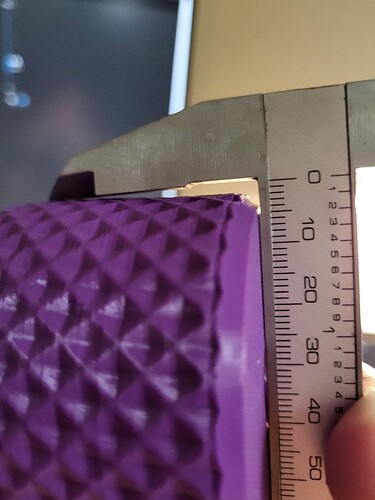
I don’t have better example right now, but you can see the gap and the “ruler” part of the calipers is flat with the print.

And on the opposite side it is square?

Printing right now calibration cube at 250% scale to be sure, should be done in 25 minutes

1 Like

Not the best quality for 1 outline and 5% infill but will do.

Same Prusa Slicer settings, same Klipper settings, almost perfectly straight, definitely not even close to previous print.

I checked Vref, 0.82V for X, 0.86V for Y, seems reasonable so didn’t change these. Steppers could be colder but not hot, drivers have little heat sinks and fan directly at them so not even warm.

Honestly I don’t have any clue, except number of outlines and infill I didn’t change anything.

Sorry for spam, but can only upload one photo in post.
Cube dimensions are also spot on, as far as I can tell with cheap calipers.

I really don’t know why some prints are perfectly fine and some are tilted only at one side.

Answer to this is missing and I think important!

The cubes look fine so far.
The model in the slicer is ok as well when the issue is present after printing it?

No it’s not, I thought it was, but after closer look it looks more like this.
image

It’s not straight on both sides but the “right” side, the one further of X0 is more angled than the one closer to X0.

Yes model in slicer looks ok and also in gcode viewer in slicer is straight, even on gcode viewer in klipper looks straight.

That is indeed very strange!
This is really the X axis? So the gantry where the print head moves left to right and vice versa?
If belts were too loose it would show more wobbles or inconsistent layers.
Real layer shifts still have equal layer widths, just shifted into direction…

And that it does not seem to be reproducible makes it even harder to diagnose.
Did you use the same speeds for the cubes and this vase/first leaned object - what are the speeds in fact?
Is this leaned object hollow or filled with infill?

Is the gantry and portal rigid enough? Or can it be easily skewed?

I assume now it’s a tilted bed or something in that direction.

Yes, X axis, one with extruder and hotend, Y in my setup is bed. I checked belts for X and Y they aren’t loose.

Yes, I used the same profile for cube and this textured round box from the first picture, only differences are a number of outlines, 3 in the box and 1 in the cube and infill 15% in box and 5% in cube.

My printing speeds are:
Inner outlines 70mm/s
Outer outlines 35m/s
Infill 100mm/s
Solid infill 50mm/s
Top solid infill 30mm/s

Frame is made out of 4020 profile with corner braces, gantry is on two 12mm steel rods, same as bed, should be rigid enough, didn’t have problems with that.

But the box on the first picture is not the first tilted object that came out of the printer. Sometimes it prints straight, like this time with the calibration cube and sometimes prints are tilted. I didn’t make any changes to hardware or structure of the printer, so I think it is issue with software or calibration somehow.

I manually levelled bed after mounting BLTouch and then run mesh bed levelling. Max delta between lowest and highest point came out around 0.1mm and I didn’t have problems with first layer adhesion, so I assume bed is levelled.

Maybe gantry and bed are tilted in the same direction, but I measured distance between bed rods and gantry rods, so gantry shouldn’t be tilted. And if it was tilted then also the cube I printed today should be tilted.

1 Like

I don’t have any idea for now. I’m not really convinced that frame or gantry is not squared as this would show up from the very beginning and I have this printer quite some time. But from luck of better ideas I will buy some bigger square/angle (don’t know correct word for that in English) to check frame/gantry/bed alignment, as the one I have is too small.

Almost a week later, but finally had some time to get back to printer. I checked it for squareness (frame, portal, gantry) and it looks ok. Nothing really sticking out. I checked if gantry is levelled and manually levelled bed with paper and then run mesh levelling again. Now bed level delta is 0.079. I printed calibration cube with the same parameters as the previous one, and it’s straight. Didn’t have time to print something more complex to check.