Right now i’m trying to make it work with BTT Octopus Pro motherboard.
Here you can’t just use FAN connector as PWM.
I’m bad in electronics, but got at last “it works! but not as i want” with help of few internet guys.
General problem comes from - Octopus in FAN connectors do not send “zero” as PWM goes “zero”, it goes “minus is disconnected”.
Simplest (but not best) solution here, comes out, is to connect “PWN minus” (or “ground”) via 10k om resistor to PWM laser pin. Also connect power source of Laser, and power source of Motherboard at “minus” output.
“PWM plus” FAN pin just not used here.
It makes laser works, but laser works “inverted”, and also (DANGER) laser goes 100% if Klipper restart MCU, or then you will turn all your thing on, laser works at 100% untill Klipper host boot up and Klipper make initialization.
Still looking for better and secure solution.
UPD:
Got try with LED_RGB pin + GND, seems works, I just add 10k resistors at both wires (just as idea of protection agains high current).
Power supplies still connected at “minus”.
There short flash of laser as all this is turned on.
Good morning,
I am also still trying to get my laser to work. I have an extra CNC pin on the board. This also supplies the laser, but I just can’t get the Printer.cfg to work. I have a BTT Manta M5P board and the Hermit Crab as a change system. But I really don’t know what the Printer.cfg should look like.
So i made my diod laser works, without “assidently turned ON” in same cases (firmare restart or sistem boot on)
My current setup is connection laser to FAN connector, but laser is inverted, so I also add enable FAN pin at firmware (its advanced option about GPIO you can find after you run “make menuconfig”).
(next is as some guy told me to do)
Here you need 1k om and 10k om resistors to be added.
Connect laser PWM pin to FAN controlled pin (what is “GND” or minus, its) via 1k resistor
Connect laser VCC (power +) to FAN pin via 10k resistor
(note: I use same power voltage for FAN and laser power)
FAN pin named VFAN is just not used !
For my case, i use Motherboard main power (24V) and second hotend connector to power a laser (12V) via DC-DC step-down converter. My diod laser drain less than 2A current.
Using hotend make you additional sure laser will be turned off, but you need add more to this config
=====================
Alternative
I also get test on LED_RGB (control pin and GND used) as PWM source. For little protection I connect both via 10k resistors. There you have no need to change example M3 M4 M5 gcode macro (what you can find in Klipper config example for PWM.
I did not check if your motherboard where support hardware PWM
btw: BTT Manta M5P and BTT Octupus have almost same schema for FAN control.
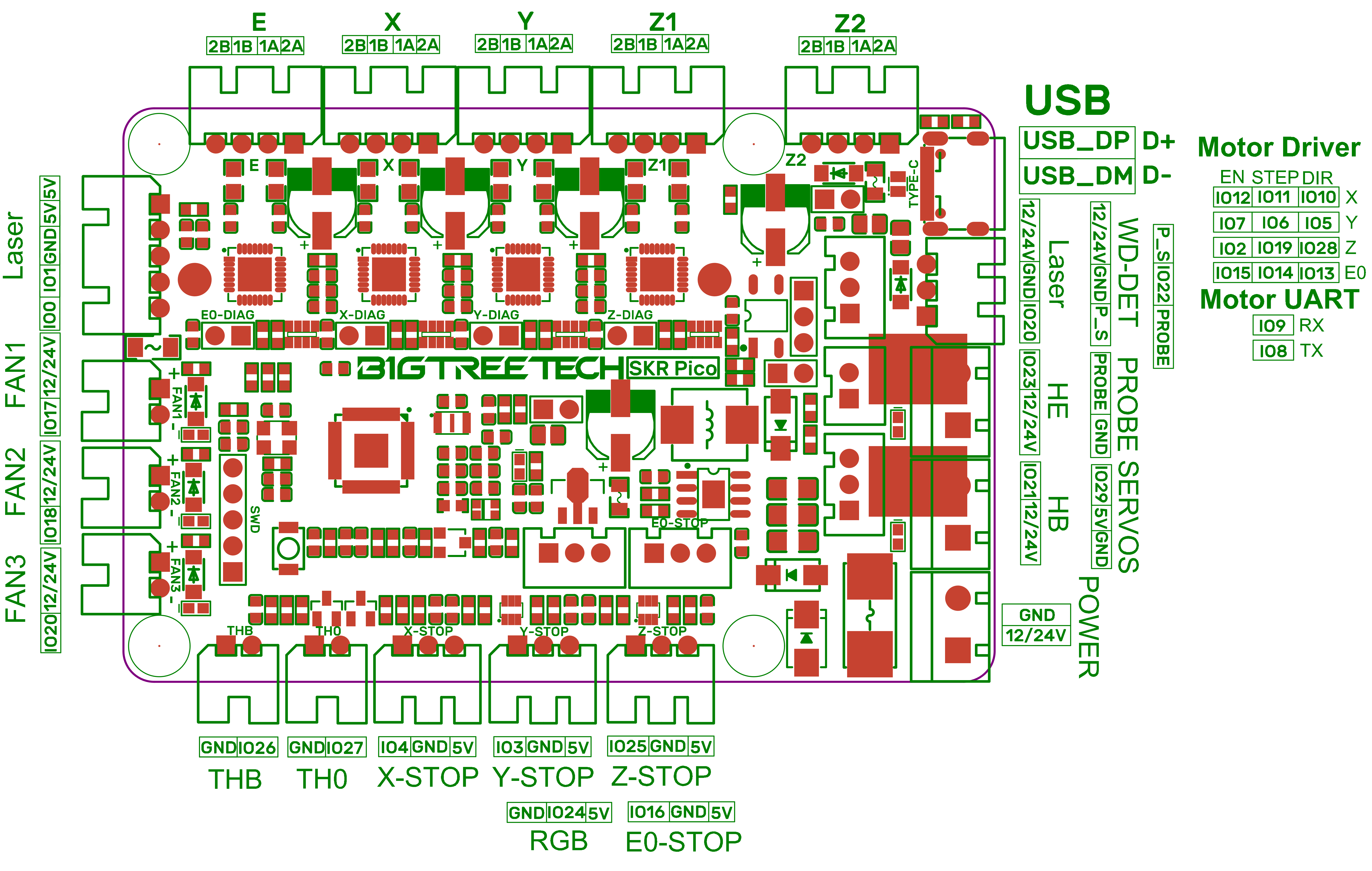
I’ve seen that the Pico board has the same pin “io20” for the laser and for the FAN3 port. When I execute the “laser on” macro, a small LED next to FAN3 port, lights up. Can you please give me some idea? I really appreciate it!
I’ve seen that the Pico board has the same pin “io20” for the laser and for the FAN3 port. When I execute the “laser on” macro, a small LED next to FAN3 port, lights up. Can you please give me some idea? I really appreciate it!
I don’t know the pico board. Do you have electrical schematics of the board to make sure gp20 is actually connected to something on the hotend you are using?
Also, like Filarius said, it is very common to have low-side switching on the FAN and other power outputs, as this has the least resistance.
My recommendation about that is that you either turn on the laser manually once the firmware has started. Sometimes the diode lasers have a button, but I prefer and suggest plugging in- and out the connection to be sure.
The other possibility is to automate that by using both the FAN pin and the Heater pin.
The heater pin would be used to enable power to the Laser / the Stepdown converter, and the FAN pin for the PWM input.
This would result in an automated way of having the laser only on when running G-Code.
Thank you for your answer!
Here is the pinout of the Pico: Pico pinout As you can see there is a dedicated port for the laser and it has the same pin io20 as the FAN3 port…
As far as i can understand, you just connect laser to laser connector and its must work. Just make sure pins are as marked, VCC on top, PWM on bottom.
Also try to check with hardware_pwm=False and cycle_time maybe 0.01
just check if its works and try with lower value of cycle_time.
On my try with BTT Octopus (stm32h723) I find it can’t switch “hardware” PWM that fast, but software PWM somekind okay.
I see you use “pwm” instead of “hardware_pwm”, as shown in later klipper examples.
P.S. To be said, as i see, skr piko do not have any protection on laser pwm pin.
EDIT:
On SKR PICO Github right now there is 3 years old firmware for Klipper, so latest pwm related update is not included.
Maybe you need to make a new firmware by yourself.
Thank you for your reply! I appreciate it!
One interesting fact is that if I use “hardware_pwm: True” I get this error:
Option ‘hardware_pwm’ is not valid in section ‘output_pin laser’
Once the underlying issue is corrected, use the “RESTART”
command to reload the config and restart the host software.
If I put just “pwm: True” (as indicated somewhere else) than I have no error but also laser not working. I must try with “False” (Really I don’t know witch one to use… maybe the Pico is capable only on software PWM)
its here said laser related pwm improvement added to Klipper itself just a half-year ago
Seems Skr Pico’s MCU is already supported by Klipper itself to make latest firmware, you just need a some Linux OS to make it. (its possible in Windows, but its not a common case).
I find guide here
Hello.
As were said, i’m another laser-on-Klipper tryer.(btt octopus stm32h723)
I get some criticue on me related to topic, from GRBL community.
Means there option where G1 command also support “S” parameter, and there “dynamic” mode - laser output (PWM) is dynamicly changes based on current speed, so light exposition on surface is going to be always same, its impotant while (de)acceleration.
Looks like this is already supported in Marlin, also with “laser mode”.
Any rumors here something same is here or will be soon in Klipper ?
Another related, if you dear, on some tests i find there short random delay on time when laser goes on/off using pwm_tool and set_pin command (software pwm). But for most cases that delay not so big, i think. Tested on software PWM. Not sure if stm23h723 actually support hardware PWM, i’m bad in reading shortcats in datasheets related but it have many “16 bit pwm timers”, but i cant find if i need choose some exact pin or its general problem in firmware
if i’m trying laser engraving with hardware_pwm=True then it can’t change PWM value many times per second.
Yes, this info I know and it is in fact the configuration we are talking about… Also I have followed the instructions for the Klipper firmware as indicated on Voron site, the only difference is that I use UART not USB connection with the Raspberry (the communication between the two modules works without problem).
I have observed now that the small LED next to the FAN 3 port is acting accordingly to the laser M3 command 0.1 - barely visible, 0.5 - half illuminated and 1 - fully on…
You can get cheapest multimeter and check voltage on connector pins (GND + PWM, GND+VCC). Also be sure laser works itselfs and VCC and PWM voltage is okay.
Like, i have diod laser already with control board there said i can use 12V VCC and 3-12V PWM, so for test i can connect VCC and GND to power source, and for test short time add same +12V to PWM.
