Flying Bear made their own version of printerboard, which well, differs from original substantially.
They refused to provide instruction how to connect original board to an printer and I’m seeking for a help. Idea is pretty simple: I want to mimic manufacturer’s version of boards as much as possible.
How to configure drivers with “jumper caps”? There are a couple of mods: "STEP/DIR Mode ", “SPI Mode”, “UART Mode”, which one to choose and how to achieve this?
Manufacturer’s version has 5 pins for fans, original only two (but also two 12/24 pins). Suppose I connected some fans to 12/24 pins, won’t this bring any problems?
My level of knowledge for printer internals is very “profound”: yesterday I discovered “jumper caps”…
Any assistance would be significantly appreciated.
You’re going to have to be a lot clearer in the situation and what you want to do.
Are you saying that you want to replace the board in the Flying Bear Ghost 6 printer with a “Robin MKS Nano V3.1” or…?
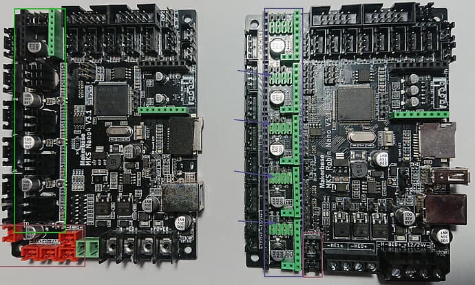
In your image, the board on the right appears to be a MKS Robin Nano V3.1 (I have one right in front of me) - I don’t know what the board on the left is. Is this the board that comes with the printer?
The two boards look similar but there could be a lot of electrical differences between them.
Yes, left → Flying Bear’s version, right → original.
I’m anxious to know all the differences, well, at least on a level which allows me to setup and connect right one to the 3d-printer itself:)
Well, how to decipher that?
Providing Cardoc “pin map” I can guess that extruder driver need to be connected in “TMC-UART” mode and “A” (what does it mean?) in “TMC-SPI” mode.
But what about X,Y,Z steppers?
What about correct position of “jumper caps” because last thing I want to do is messing with heart of the machine.
I can’t find any detail on the Nano4 but I’m 95% sure the only real difference it the “4” has drivers soldered on and the “plain Nano” has sockets. The Marlin source code uses the same settings as a “plain Nano 3.1”
Did you buy driver boards? The Nano won’t work without them.
What board you actually have in your printer. Is it an MKS Robin Nano V3.1 or the other one in the image above?
What are your stepper drivers. If it’s an MKS Robin Nano V3.1 then you have stepper driver modules (small PCBs) that you need to identify. If it’s the other board, you’ll have to figure out what was provided.
I did a quick run through the “Ghost6 Manual” in the link that @cardoc provided and there’s not a lot of useful information there.
I’ve never heard of a MKS Robin 4 - I’m not sure where you got that term.
There are some pretty significant differences between the two boards - the one on the right has three power transistors while the one on the left has two - looking at the Screw Terminals, for the one on the right there two for “HE#” and none on the board on the left. There is a different number of 3 pin JST XH connectors across the top between the two boards. Finally, there I know they both have “Makerbase MKS Robin Nano V3.1” on the silkscreen, but I wouldn’t count on the pin mappings to be identical for both boards (in light of what I see in the two images).
The big thing is for @reactive to identify which board is in his printer. If it’s the same as the one on the right, then we can walk him through it. Otherwise, he should be reaching out to Flying Bear to understand the board he has.
If this is correct, then do you have five empty green/black sockets on your board (going up the left side of the right board in image above)?
If these sockets are empty then you should look for something like BTT (BigTreeTech) TMC2209 V1.3 (which is the latest version) driver modules. I don’t know where you live but I would recommend Amazon as you could have them tomorrow.
You should order five of them; I’m not sure if you need all slots filled for your printer so I’m recommending you buy five as they’re pretty cheap.
First, decide on which of the five sockets you are going to use. As you’re new to Klipper, I recommend that you wire things as shown on the board itself and used in the printer originally (ie wire the X Axis Stepper to the X Axis Driver, etc.).
Before putting the driver into the socket, you will need to put a jumper to make the UART connection between the MCU and the TMC2209. To do this, follow the instructions here:
Now, I don’t believe that you are going to use sensorless homing.
But, you do need to specify the voltage used by the stepper motor drivers with a jumper. I used 3.3V when I used the MKS Robin Nano V3.1 and TMC2209s. This is point 2 in the image below:
Finally they arrived and I have time to play with them:)
I changed terminals lugs from “fork” to “pin type” for power, bed and hot-end
I connected both coolers(3040 and 4040) to corresponding fan-pins and for I utilized 12/24v pins for “board-cooler” and “case-one”. Tiniest fan simply doesn’t have another fan-pin, but maybe there’s a way to utilize power-detector/filament2-detector pin?!
Setup UART mode and 3v power for drivers. By the way, these 2209 drivers also have some pins. Should I consider anything about them?
I had all configs in klipper and used it to make&flash printerboard. Can all those settings be re-used?
Could you provide more information? I’m not sure if you’re saying that there isn’t a fan driver available or an appropriate socket for it.
Make sure your power is correct for your fans (ie 12V power is driving 12V rated fans).
Nope leave them be. They’ll plug into their respective sockets on the board.
Nope. You’ll have to create a new printer.cfg Look for an example for the board with your printer to start. At the very least, get the example printer.cfg for the Robin Nano V3.1 and use that.
Check the voltage ratings of the fans to the voltage going into the board - if they’re the same then you can power on and load Klipper. Once Klipper is installed we can work through the printer.cfg issues.