Stepper Motors in 3D Printing: Characteristics & Practical Guidelines
1. Motor Quality Matters
- Impact: High-quality stepper motors - characterized by tighter manufacturing tolerances, superior bearings, and consistent magnetic properties - offer greater precision, smoother motion, and lower vibration.
- Takeaway: Investing in reputable motors establishes a reliable performance baseline and often makes tuning easier (or even unnecessary).
2. Key Stepper Motor Characteristics
2.1 Inductance (L)
-
Definition: Inductance (measured in millihenries, mH) indicates a stepper motor’s ability to resist changes in current.
-
Practical Impact: Lower inductance enables faster current changes, supporting higher speeds and more responsive movements - crucial for X and Y axes during rapid travel. High inductance slows current changes, limiting top speed and torque at high RPM and making it harder for the driver to regulate current precisely.
-
Recommendations:
- For X/Y axes, use low inductance motors (<<4 mH, high-speed ~2.5 mH or lower) to maximize speed and torque.
- For Z, a slightly higher inductance is acceptable due to slower movement, but avoid extremely high values.
- For extruders, low inductance improves responsiveness for retractions and filament control.
2.2 Rated Current (I)
-
Definition: The maximum continuous current the motor windings can safely carry, measured in amperes (A). Motor datasheets typically provide this value.
-
Practical Impact: Higher rated current allows greater torque, vital for fast axis movement and resisting extruder back-pressure, but also increases heat.
-
Recommendations:
- X/Y axes: ≥1.2A rated current for consistent dynamic torque.
- Z axis: Sufficient current for holding torque with heavier beds.
- Geared extruders: Lower current may be sufficient (~500mA), but direct-drive extruders benefit from higher current motors for more torque.
2.3 Root Mean Square (RMS) Current
-
Definition: RMS current reflects the effective steady-state current delivered under dynamic operation - essentially, the AC equivalent of DC current.
-
Practical Impact: Klipper specifies
run_currentin RMS, since stepper drivers regulate current in a sinusoidal waveform rather than constant DC. -
Recommendations:
- Calculate RMS as:
I_{RMS}= \frac{I_{max}}{\sqrt{2}}\approx I_{max} \times 0.707- Set
run_currentto 80-100% of the calculated RMS value, balancing torque with manageable heat:run\_current = I_{RMS} \times (0.8 \dots 1.0)
2.4 Winding Resistance (R)
-
Definition: The resistance of the motor’s coils, measured in ohms (Ω).
-
Practical Impact: Lower resistance means less heat loss and better current delivery at speed. High resistance can limit maximum current and cause overheating or underperformance.
-
Recommendations:
- Choose low to moderate resistance motors, i.e. 1.2 Ω to 3 Ω
- A sound relationship between current, voltage and resistance can be defined asI_{max} \times R < 0.3 \times V_{Supply\ Voltage}
2.5 Supply Voltage
-
Definition: The voltage supplied to stepper drivers - commonly 24V in modern 3D printers.
-
Practical Impact: Higher voltage enables stepper drivers to overcome inductance and back-EMF, supporting higher speeds and torque.
-
Recommendations: Use a 24V (or higher) power supply if supported, especially for low-inductance or 0.9° stepper motors. This is vital for high-speed X/Y or extruder use.
2.6 Rated Motor Voltage
-
Definition: The voltage at which the motor is designed to operate continuously, typically ranging from 2 to 5 V for common stepper motors.
-
Practical Impact: Modern stepper drivers are sophisticated current controllers. They use the high supply voltage (e.g., 24V) and rapidly switch it on and off (a technique called PWM or ‘chopping’) to precisely maintain the target current value. The motor’s low rated voltage (e.g., 2.8 V) is not a supply requirement; rather, it indicates the voltage needed to push the rated current through the coil under simple DC conditions.
-
Recommendations: Use a 24 V (or higher) power supply to give the stepper driver the voltage “headroom” needed for fast current rise and optimal control - especially during rapid accelerations and high-speed movements. The supply voltage should always be significantly higher than the motor’s rated voltage for best performance in 3D printing.
3. 0.9° vs. 1.8° Stepper Motors: Choosing for Your Application
3.1. Resolution and Precision
-
0.9° motors provide double the step resolution (400 steps/rev) versus 1.8° motors (200 steps/rev).
-
This translates to greater positional accuracy, smoother movement, and reduced artifacts (VFAs), especially on the X/Y axes and for direct-drive extruders.
3.2. Microstepping: Benefits and Realities
-
Microstepping divides each full step into smaller “microsteps” for smoother motion and less vibration.
-
Reality check: While microstepping greatly increases addressable positions (apparent resolution), actual mechanical accuracy is still limited by the motor’s physical step size and construction. Increased microstepping can reduce “stiffness” between full steps, making these positions more susceptible to disturbance.
-
Example: A 0.9° motor at 1/16 microstepping and a 1.8° motor at 1/32 both achieve 6400 microsteps/rev - but the 0.9° retains better mechanical “anchoring” per microstep.
3.3. Torque Characteristics
-
Holding Torque: 0.9° motors may have slightly lower rated holding torque than 1.8° models of the same size, but quality 0.9° motors can match or surpass some 1.8° options.
-
Torque Stiffness: 0.9° motors offer better corrective torque for fine position errors, leading to crisper, more accurate movement during acceleration, deceleration, and rapid load changes.
-
Microstepping Effect: Per-microstep torque drops with more microstepping, but total rotational torque is largely unchanged during normal movement.
3.4. Speed and Electrical Considerations
-
0.9° motors require twice as many step pulses per revolution - so they rotate at half the speed of a 1.8° motor for the same pulse rate.
-
For the same velocity, the printer board needs to calculate twice the number of step pulses for a 0.9° motor. This necessitates sufficient computational power, especially for high velocities or accelerations.
-
Their higher inductance and back-EMF require higher voltage (24 V+) to maintain speed and torque.
-
1.8° motors can operate acceptably on 12 V, may offer slightly more holding torque for the same frame size, and can reach higher speeds when limited by controller frequency or voltage.
3.5 Takeaway
0.9° motors deliver measurable improvements in print quality, precision, and extruder performance - especially when used with 24 V supplies and well-tuned drivers. Microstepping boosts smoothness and quietness for both motor types, but true mechanical accuracy depends on the motor’s physical construction. 1.8° motors remain a robust, economical choice for non-critical axes or when high speeds or low voltage operation are priorities.
4. Stepper Motor Temperature: What’s Normal?
It’s a common misconception that stepper motors should remain cool. In reality, stepper motors are designed to run hot - and elevated temperatures often indicate adequate current for rated torque. Following safety limits are defined by the insulation class of the windings.
- Class B (130 °C): Most consumer 3D printer motors; safe for up to 130 °C internal, which may equal 80-100 °C on the case.
- Class H (180 °C): Found in some industrial or specialty printers; shell temps can safely reach 130 °C or more.
Warning: Consider Heat in Your Mechanical Design
- Mounting Materials: Ensure your motor mounts are made from materials that can withstand these temperatures without deforming - many plastics (even ABS/ASA) may be insufficient.
- Extruder Heat Creep: Heat from the extruder motor can transfer into the cold end, softening the filament path and causing jams or extrusion issues. Ensure your extruder design can cope with the heat creep. Installing additional heatsinks or even lowering the run current might be necessary.
4.1 Takeaway
A motor case temperature of 60-80 °C during continuous operation is normal and expected. If the motor is only slightly warm, it is likely underdriven (i.e., run_current set too low), reducing torque and risking skipped steps. Don’t reduce motor current simply to lower temperature; this sacrifices reliability and print quality.
5. Matching drivers to stepper motors
Understanding the relationship between a stepper driver, such as a TMC driver, and the stepper motor is crucial for efficient and accurate operation and performance.
5.1 Drivers Are Current Regulators
-
How They Work: Drivers use chopper control to regulate current, not just voltage. They convert your PSU voltage into finely controlled current through the coils, enabling smooth microstepping and quiet motion.
-
Takeaway: The driver’s ability to precisely regulate current is the core of its performance. This control is only as good as the match between the driver and the motor.
5.2 Match Driver and Motor Currents Carefully
-
Common Mistake: Using a high-current driver (e.g., 6 A) with a low-current motor (e.g., 800 mA).
-
The Problem - Inaccurate Sensing: A driver designed for high current uses a low-value sense resistor. When measuring the low current required by a smaller motor, the resulting voltage drop across this resistor is tiny, making it difficult for the driver to sense the current accurately.
-
Symptoms: This mismatch leads to poor current waveform fidelity, high ripple, step inaccuracies, and degraded performance, especially in silent or high-precision modes.
-
Takeaway: Choose a driver whose effective current control range matches the motor’s rated current. Ideally, the motor’s rated current should be 70-85% of the TMC driver’s maximum current rating as determined by its sense resistor.
6. Connecting the Motor to the Printer Board
Stepper motor connections in 3D printers are not standardized across brands, boards, or even within one manufacturer. Whenever changing printer boards, motors, or motor cabling, it is essential to carefully verify the wiring assignments to avoid malfunction or hardware damage.
6.1 Motor Phases and Direction
A typical bipolar stepper motor has two phases, each with two wires (total: 4 wires). This configuration is illustrated in the following image:

-
Phases: The two coil pairs (marked with green and orange rectangles) must be correctly connected to the printer board. The sequence of the phases (whether a coil is designated as A or B) does not affect operation, only the rotation direction.
-
Identifying Phases: If the datasheet or manufacturer’s wiring diagram is unavailable, you can determine the coil pairs as follows (with the motor not connected to the board):
- Digital Multimeter (DMM): Set to resistance mode. The two wires from the same phase will show the winding resistance (typically a few ohms). Unconnected wires will show infinite resistance.
- Manual Turning: Rotate the motor shaft by hand. Then, short any two wires together and rotate again - if it feels noticeably harder, those two wires form a phase.
-
Polarity and Rotation Direction:
Polarity within a phase (BLK/GRNrespectivelyRED/BLU) and phase sequence (A/B) define the rotation direction. This can easily be swapped by inverting the direction in firmware (e.g., Klipper’sdir_pinsetting) and is not critical to correct at the wiring stage.
6.2 Connector Markings on the Board
Board manufacturers use various notations, most commonly a combination of A/B (or 1/2) and numbers (e.g., A1 A2 B1 B2, or 1A 1B 2A 2B). Markings may differ even within the same brand or board family. The following image shows two different stepper connectors side by side:
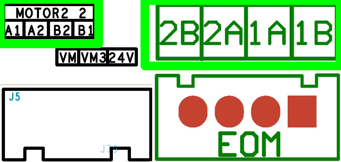
- Phases: The first character in the board labeling typically groups wires by phase.
- Harnesses: Inspect the motor wire harness carefully - some detachable harnesses internally cross or swap pins. There may not be a direct one-to-one mapping between the connector ends.
6.3 Takeaway
There is no universal wiring standard for stepper motors or printer boards. Double-check all assignments:
- Incorrect phase wiring will prevent the motor from moving properly and can cause driver errors or damage.
- Example TMC error messages indicating phase issues:
s2vsa=1(ShortToSupply_A!) ola=1(OpenLoad_A!) olb=1(OpenLoad_B!) - Always validate wiring after any hardware change or when assembling custom wiring.
- When in doubt, check the wiring with a multimeter and reference both the motor and board pinouts against the relevant datasheets, schematics, and documentations.
7. Wiring Stepper Motors in Series or Parallel
Sometimes, it’s necessary to drive two stepper motors from a single driver—commonly seen on 3D printer Z-axes with dual motors, or when controller outputs are limited. The two primary wiring options are series and parallel connection. While these methods may seem interchangeable, they have distinct impacts on motor performance, control, and reliability.
Note:
- The following assumes identical motors; however, this does not exist. Typical manufacturing tolerances for motors, regarding their electrical and mechanical characteristics, are in the range of ±10% to ±20% on their rated datasheet values.
- Neither wiring scheme is ideal compared to giving each motor its own driver. Both approaches introduce compromises, and careful consideration is needed before implementation.
7.1 Series Connection – Characteristics & Effects
In a series connection, current flows sequentially through both motors for each phase.
- Total Resistance: Adds together:R_{series} = R_{motor1} + R_{motor2} = 2 \times R
- Total Inductance: Adds together:L_{series} = L_{motor1} + L_{motor2} = 2 \times L
- Voltage: The supply voltage is divided between the two motors; each gets about half (assuming identical motors).
- Current: Both motors receive the same current, regulated by the driver.
Practical effects:
- Torque: Both motors can produce full torque, since current is maintained.
- Dynamic Performance: Significantly limited. Double the resistance and inductance means current rise/fall is much slower, causing torque to drop off at higher speeds. This makes series wiring suitable mainly for low-speed axes (e.g., Z-axis).
- Voltage Supply: To offset reduced performance, a higher supply voltage (ideally doubled) can help restore some lost speed/torque capability.
- Reliability: Motors remain well-synchronized, and step loss due to current imbalance is less likely.
7.2 Parallel Connection – Characteristics & Effects
In a parallel connection, each motor is wired directly to the driver outputs - both motors see the full supply voltage, and the current splits between them.
- Total Resistance: Halved:R_{parallel} = \frac{R}{2}
- Total Inductance: Halved:L_{parallel} = \frac{L}{2}
- Voltage: Each motor receives the full supply voltage.
- Current: The driver must supply twice the current (for identical torque per motor).
Practical effects:
- Torque: Parallel connection theoretically preserves high-speed torque thanks to lower total inductance and resistance.
- Dynamic Performance: Can match or exceed a single motor, but only if driver current capability is sufficient.
- Driver Load: For the same torque, the current requirement is doubled; most stepper drivers cannot safely provide this much current, risking overheating or damage.
- Control & Balance Issues: In reality, no two motors are perfectly matched. Even slight differences cause uneven current distribution, leading to lost steps, uneven torque, and problems with advanced driver features (like CoolStep). Risk of desynchronization or excessive vibration is much higher.
7.3 Takeaway
- Series connection is the lesser evil and is acceptable for low-speed axes (such as Z-axes in 3D printers), where speed and high dynamic response are less important.
- Parallel connection should generally be avoided. It puts more strain on the driver, makes thermal management harder, and risks reliability problems due to current imbalance.
- Best practice: Always use a dedicated driver for each stepper motor when possible. This ensures maximum performance, reliability, and compatibility with advanced control features.
8. Advanced: The Importance of Supply Voltage
The supply voltage is key to achieving dynamic and well-controlled stepper motors, yet its importance is often neglected or underestimated. Supply voltage is “consumed” by multiple factors discussed in previous chapters, potentially leaving insufficient voltage to drive the required current through the motor coils.
8.1 Back-EMF
When the motor spins under the stepper driver’s power, its coils cut through magnetic field lines. This movement induces a voltage opposite in direction to the driving voltage, reducing the net voltage across the coils and thus the current. This is called Back-EMF.
-
Faraday’s Law of Electromagnetic Induction: Any change in magnetic flux through a circuit induces an electromotive force (EMF). In motors, this is the voltage generated in the coils as a result of the motor’s rotation in a magnetic field. The amount depends on:
- Number of turns in the coil
- Rate of change of magnetic flux (i.e., speed of rotation)
-
Lenz’s Law states that the direction of the induced EMF always opposes the change in magnetic flux that produced it. In motors, this means back-EMF always acts against the applied voltage causing the rotation - hence the term “back” EMF.
-
Back-EMF depends on several factors and increases with:
- Rotational Speed (\omega): Faster spinning = greater back-EMF.
- Magnetic Field Strength (\Phi): Stronger magnets = more EMF for a given speed.
- Number of Turns (N): More coil turns = higher EMF.
- Motor Geometry/Design (k_e): Shape and structure also affect the outcome.
8.2 Inductive Voltage Drop
A similar effect arises from the pure inductive nature of the motor’s coils. An inductor resists changes in current, requiring additional voltage to force these changes.
Inductive voltage drop is influenced by:
- Motor inductance
- Rotation speed of the shaft
- Motor step angle (e.g., 0.9° or 1.8° - see
full_steps_per_rotationin Klipper)
8.3 Resistive Voltage Drop
This loss is simply the product of the winding current and coil resistance (Ohm’s Law). It is mostly constant for a given current.
8.4 Other Voltage Losses
Other losses can include:
-
Driver Efficiency & Overhead: Stepper drivers (A4988, TMC2209, DRV8825, etc.) have internal voltage drops (e.g., MOSFETs, current sense resistors) and require some “headroom” for proper regulation, especially at high step rates.
-
Noise & Spikes: Fast current transitions, long wires, and PCB layout can introduce voltage spikes and transients.
-
Supply Tolerance: Supply voltage may sag under heavy load or fluctuate due to other system components.
-
Core (Iron) Losses: This leads to hysteresis and eddy current losses in the iron. These iron losses grow with the frequency and magnitude of flux change and mainly contribute to motor heating.
These losses are difficult to quantify precisely, but should be considered in a robust design.
8.5 Order Of Magnitude and Effects
Back-EMF and inductive losses are typically the dominant voltage consumers, largely dependent on printing speed and microstepping. Resistive loss is constant but may also consume a few volts. The “other” losses are hard to quantify but not negligible.
-
Total Required Voltage: The absolute minimum voltage required to drive the motor is the sum of all losses (Note: This is a simplification, since the losses sum as vectors):
V_{Required} = V_{Back−EMF} + V_{Inductive} + V_{Resistive} + V_{Other}
-
Typical Range: The required voltage can range from 5 V to 35 V, depending on motor, speed, and configuration, and must be calculated carefully.
-
Effective Voltage: The voltage effectively available as margin is:
V_{Effective} = V_{Supply} - V_{Required} -
The Speed Limiter: If V_{Effective} approaches zero or even becomes negative, the system cannot maintain the required current, causing a sharp drop in available torque - this is the primary factor limiting a stepper’s maximum speed.
Important: Leave a Safety Margin
- While the main contributors can be calculated accurately, other system losses are hard to determine.
- Good engineering practice: Do not let total calculated losses exceed 80-85% of the supply voltage. This leaves reserve to handle “other” losses, voltage drops, and noise.
8.6 Calculation
To quantify the voltage losses discussed, you can use the attached OpenOffice Calc spreadsheet. This tool will help you calculate the back EMF and the resulting voltage drop across the motor windings.
Calculate_Back-EMF_And_Voltage-Drop.ods (7.5 KB)
Notes on Using the Calculator:
-
Units: Pay close attention to the units required by the calculator. Motor datasheets often use inconsistent units (e.g.,
mHvs.H,Nmvs.oz-in).
Ensure all values are converted to the correct units for accurate calculations.
Where possible, values can be taken directly from your Klipper configuration. -
Kinematics-Specific Speeds (CoreXY/H-Bot): For kinematics like CoreXY, the motor speed can be significantly higher than the nozzle’s print speed, especially during diagonal moves.
For the worst-case motor speed during a 45° diagonal move, use:v_{motor} = v_{print} \times \sqrt{2} \approx v_{print} \times 1.414Use this higher motor speed in the spreadsheet to assess true voltage requirements.
-
Interpreting the Results:
- The calculation models only the maximum torque at each speed permitted by voltage limitations (using the vector sum).
- It assumes perfect current control up to the voltage boundary (as provided by modern chopper drivers).
- Mechanical and dynamic effects (resonance, damping, load inertia, friction) are not included.
- At low speeds, real motors lose torque due to resonance and dynamic effects (such as “mid-band instability”), even when current is available.
- Datasheet curves are measured by increasing load on a running motor until it stalls at each speed. This includes effects like mechanical resonance, system inertia, friction, but unfortunately rarely the driver/motor matching. Using them is clearly preferred over theoretical calculations.
- In practice, stepper torque can drop in the first 50–100 mm/s (typical for 3D printer steppers), even before voltage starvation occurs. Additionally, after voltage starvation begins, it does not necessarily mean that the torque has already dropped to a critical minimum.
8.7 Available Torque
A motor’s torque is the rotational force it can exert to overcome mechanical resistance. In 3D printing, this resistance is primarily due to:
- Inertia: Resistance of the axis to changes in velocity (especially during acceleration) and mainly influenced by the mass of the axis.
- Friction: Friction in linear motion components (e.g., bearings and rails).
- Unexpected Events: Obstructions such as the nozzle hitting a warped part or “plowing” through dense infill.
The torque a motor can deliver depends on its rotational speed. Manufacturers illustrate this with a pull-out torque curve, essential for understanding real-world motor performance.
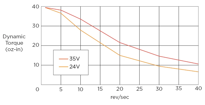
(Source: Stepper motors: is high torque at high speeds possible?)
This curve shows the maximum usable torque at each speed. The decrease in torque at higher speeds is due to voltage losses (mainly back-EMF and inductive effects).
For reliable operation, the required torque to move an axis must stay comfortably below the pull-out torque curve. If the required torque at a given speed exceeds available torque, the motor will stall or skip steps - leading to a failed print. Any operating point below the curve is safe.
8.8 Takeaway
This overview is meant to provide a practical understanding of stepper motor physics. Reality is even more complex and only partially captured by theoretical calculations.
- Modern Stepper Drivers: The drivers and higher supply voltages significantly increase achievable speeds and torque.
- Supply Voltage: Supply voltage is crucial for dynamic response. Using voltages even beyond 24 V can make sense for high-speed printers - but very high voltages (like 48 V+) may introduce issues such as increased heat, voltage ripple and more demanding electrical design.
Rule of thumb: Use a supply voltage 8 - 10 times the motor’s rated voltage. - Torque Budget: Available torque at higher speeds may still be sufficient for 3D printing, but always leave a margin. In fact, the torque needed to purely accelerate an axis (not accounting for other torque “consumers”) is less than one might think in a 3D printer.
Rule of thumb: Design for at least 30% more torque than the calculated worst-case load, however determining the worst case can be challenging. - Overall System Design: Careful matching of mechanical and electrical parameters is key. Optimize for the entire system, not just the motor or driver in isolation.
9. Forcibly Moving a Connected Stepper Motor: Voltage Generation
When you manually rotate a stepper motor (even when powered off), you turn coils in a magnetic field - using the motor as a generator.
- The faster you turn the shaft, the higher the voltage generated across the coils.
- This can be increased by gearing or a small `rotation_distance.
- Polarity and magnitude depend on speed and direction.
This is Faraday’s Law in action: the changing flux through the coils induces a voltage proportional to the speed of shaft rotation and the other factors above.
- Overvoltage: The generated voltage may exceed maximum ratings for stepper driver inputs, MOSFETs, or logic circuits. Current may flow “backwards” into power rails, damaging regulators, microcontrollers, or causing erratic behavior.
- Fast, forceful spinning (e.g., yanking the gantry or extruder by hand) can easily generate 10 V+ - sometimes 20-40 V - which may exceed driver and board ratings.
- Some boards/drivers offer protection, but you should not rely on it. Slow, gentle movement by hand is generally safe.