CAN Basics
Table of Contents
- The Control Area Network (CAN) Bus
1.1. Pros and Cons of CAN in 3D Printer
1.2 General CAN Concept
1.3 General Wiring of the CAN Bus for a 3D Printer
1.4 Recommended Wiring Lengths - Klipper Architectures with CAN
2.1 Standalone CAN
2.2 USB to CAN Bridge
1. The Control Area Network (CAN) Bus
The Control Area Network (CAN) bus is a serial bus protocol. All nodes connected to this bus system can exchange data with each other. Originally developed for the automotive sector, it was designed to simplify a car’s electronics and the need for information exchange. Since then, this bus protocol has been adopted in various contexts due to its robustness and simplicity.
One of these new contexts is its use for connecting various peripherals in a 3D printer system, such as in Klipper.
1.1. Pros and Cons of CAN in 3D Printer
Pros:
- Simplifies wiring, e.g., all wires that would typically lead to the tool-head are replaced by 2 wires for the CAN bus plus 2 wires for power supply.
- Especially suited for scenarios where wiring is difficult (space constraints) or the cable is subject to constant moving and bending, e.g., on a tool-head. Regular USB cables do not handle this type of strain very well.
- Easily extensible.
Cons:
- Adds additional setup complexity. Often, it is easier to just plug in another USB board.
- Adds additional points of failure.
Other:
- Not suitable for use within heated chambers, at least if the temperature rises above around 80 °C - 100 °C. This is not a limitation of the CAN bus itself, but rather of the additional electronic components that are often not rated for these temperatures.
1.2 General CAN Concept

The above schematic shows the general layout of a CAN bus system:
- Data is transferred via two wires (and GND, which is omitted for simplicity). These two lines are called CAN H and CAN L.
- Each participant to the bus is called a Node.
- The “pure” CAN does not provide means to identify devices on the bus. Klipper introduces a Universally Unique Identifier (UUID) to unequivocally identify the nodes on the bus. This UUID is also used in the
printer.cfgto address the respective node. - All Nodes on a bus are equal; there is no “master controller” or central management device.
- Nodes typically contain three functional blocks, with two of them integrated into the Micro Controller Unit (MCU):
- CAN Software: The MCU runs CAN-aware software or an application. It manages the information that is either received from the bus or to be sent over the bus. In this context, this is the Klipper firmware.
- CAN Hardware: Many modern MCUs have an integrated function block to handle the CAN protocol. One exception is the RP2040, which lacks this block in its hardware. Here, this functionality is implemented in software using the can2040 software (no user interaction is needed, as Klipper installs this software automatically).
- Transceiver: This is a separate chip. On one side, this transceiver connects directly to the bus and manages the TRANSmission and reCEIVING of data packets on the bus. On the other side, it connects to a CAN Hardware block that is implemented in the Micro Controller Unit (MCU).
- To prevent reflections and ringing on the bus, the start and end of the bus are terminated with 120 Ω resistors. The resistors also ensure that the CAN lines are pulled to the correct state. The correct termination is of key importance for a working CAN bus.
1.3 General Wiring of the CAN Bus for a 3D Printer
Depending on the data rate, the length of a CAN bus can reach up to 500 m, and still up to ~40 m for 1 Mbit/s data rates that are typically used in Klipper. Because 3D printers typically use significantly shorter bus lengths, the mandatory requirements are less stringent.
Mandatory Requirements:
- The bus needs to be properly terminated on both ends with 120 Ω resistors. Typically, this is done on the first and last CAN device by setting appropriate jumpers in the hardware.
- As with every other connection, it must have solid contact, especially on crimped connectors.
- On moving cables, the cables should have a quality that allows for continuous bending. This does not necessarily mean that one needs to use drag-chain certified cables.
Other Considerations:
- The applicable standards require cables with twisted pairs.
- Using high-end, shielded, twisted pair, and drag-chain certified cables is the optimal solution, although it may also be an inefficient use of money.
- The default topology for CAN is a linear bus from one device to the next. A star topology is possible, but may introduce additional challenges and hardware requirements. This is beyond the scope of this article.
- The wiring length between the actual bus and a node is called stub-length.
1.4 Recommended Wiring Lengths
The following table lists some very general recommendations for the lengths of the wirings. The values have been established mainly based on the information in:
- ISO-11898-1, -2, -3
- CiA 303-1
- Information from the CAN-Wiki
| CAN Type | Bitrate | Max Individual Stub Length | Max Cumulative Stub Length | Bus Length |
|---|---|---|---|---|
| High-Speed CAN (ISO 11898-2) | 1 Mbps | 0.3 m | 2 m | 40 m |
| High-Speed CAN (ISO 11898-2) | 500 kbps | 1 m | 5 m | 100 m |
| High-Speed CAN (ISO 11898-2) | 250 kbps | 3 m | 10 m | 250 m |
| Low-Speed Fault-Tolerant CAN (ISO 11898-3) | 125 kbps | 6 m | 30 m | 500 m |
Explanation of Columns:
- Bit Rate – The data transmission speed in bits per second.
- Max Individual Stub - Length in meters between the linear bus and the drop to a node.
- Max Cumulative Stub - Length in meters of all stubs added up
- Bus Length - Total length [m] of the entire bus.
Key Takeaways:
- The values given here are based on relevant standards and should be considered guidelines. Information in the CAN-Wiki suggests that real-world lengths may be considerably shorter.
- Values depend on the transceiver used and need to be calculated individually according to the manufacturer’s data sheet or application note for highest precision or stability.
- The Cumulative Stub Length reduces the overall Bus Length.
- It is very important to try to maintain a linear bus topology. Stubs should be as short as possible.
- Environmental factors, used hardware and contributors can shift these boundaries in either direction. Noteworthy factors include cable quality, which influences propagation delay, and EMI effects, among others.
2. Klipper Architectures with CAN
In the setup and configuration, Klipper differentiates between two types of CAN architecture:
- CAN Nodes (e.g., tool-boards) connected to a standalone CAN Adapter Module.
- CAN Nodes connected to a CAN-enabled “master printer board,” the so-called CAN to USB Bridge.
2.1 Standalone CAN
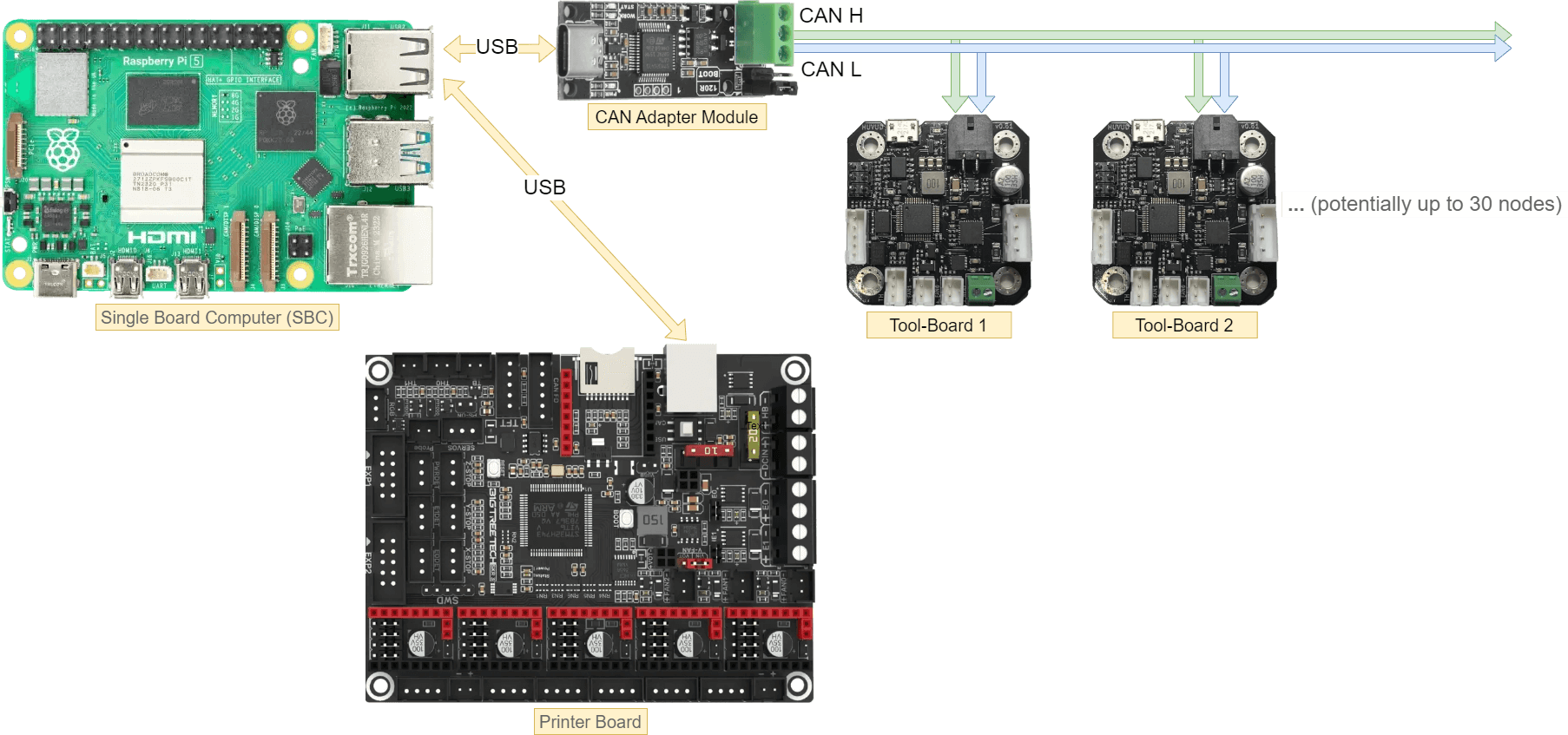
Description:
- A CAN Adapter Module is connected via USB to the SBC and is the “start” of the CAN bus.
- This adapter needs to be terminated to 120 Ω by setting respective jumpers on it.
- From this adapter, two wires (CAN H and CAN L) will start the CAN bus.
- One or multiple further CAN boards, e.g., tool-boards, are connected to this adapter.
- The boards “in the middle” of the CAN bus must not be terminated.
- The last board at the end of the CAN bus must be terminated to 120 Ω by setting respective jumpers on it.
- Another printer board that supplies the rest of the printer’s hardware is traditionally connected via USB to the SBC.
- Not shown: The printer board and all the CAN boards need a connection to the main power supply unit of the printer.
2.2 USB to CAN Bridge
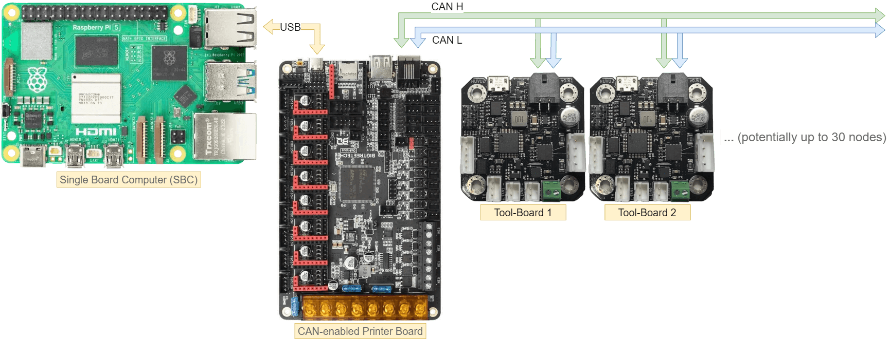
Description:
- A CAN-enabled “master printer board” with a dedicated CAN connector is connected via USB to the SBC.
- This “master printer board” supplies the most printer peripherals and also serves as the starting point of a CAN bus.
- From its CAN connector, two wires (CAN H and CAN L) will start the CAN bus.
- This board needs to be terminated with 120 Ω by setting respective jumpers on it.
- One or multiple further CAN boards, e.g., tool-boards, are connected to this “master printer board.”
- The boards “in the middle” of the CAN bus must not be terminated.
- The last board at the end of the CAN bus must be terminated with 120 Ω by setting respective jumpers on it.
- Not shown: The printer board and all the CAN boards need a connection to the main power supply unit of the printer.
(Diagrams created with draw.io - CAN_Basics.zip (593.0 KB))