CAN network failures - M8P CB2 EBB42

In case it helps:

I’m not sure where you find any CAN errors in your logs.
Again, the sequence of events is:

  1. The system fails with “MCU ‘mcu’ shutdown: Missed scheduling of next digital out event”
  2. All errors logged after this initial error and up to the next restart are to be disregarded
  3. The attempt to reconnect fails, but it fails for the main MCU, which supports the theory that the “something” caused “something else” which now thwarts new connections and is only cleared with a hard cycle. This could be the main MCU stuck in a bad state or something on the OS or networking level around the CAN interface.
    mcu 'mcu': Starting CAN connect
    Created a socket
    webhooks client 547752869312: New connection
    webhooks client 547752869312: Client info {'program': 'Moonraker', 'version': 'v0.9.3-100-gcea6fbc'}
    mcu 'mcu': Timeout on connect
    Created a socket
    mcu 'mcu': Wait for identify_response
    Traceback (most recent call last):
      File "/home/biqu/klipper/klippy/serialhdl.py", line 68, in _get_identify_data
        params = self.send_with_response(msg, 'identify_response')
      File "/home/biqu/klipper/klippy/serialhdl.py", line 262, in send_with_response
        return src.get_response([cmd], self.default_cmd_queue)
      File "/home/biqu/klipper/klippy/serialhdl.py", line 322, in get_response
        self.serial.raw_send_wait_ack(cmds[-1], minclock, reqclock,
      File "/home/biqu/klipper/klippy/serialhdl.py", line 254, in raw_send_wait_ack
        self._error("Serial connection closed")
      File "/home/biqu/klipper/klippy/serialhdl.py", line 61, in _error
        raise error(self.warn_prefix + (msg % params))
    serialhdl.error: mcu 'mcu': Serial connection closed
    mcu 'mcu': Timeout on connect
    

And again, for the avoidance of doubt: These messages mean nothing else but “I tried to connect but nobody answers” from the perspective of Klipper. It does not contain any indication why.

So is this the end of any help I can expect to receive?

I understand what you are saying, and I agree that the CAN messages only show that an expected communication was missed. Again, this is the only “error” message that appears in the log. I agree that there is no indication in the log as to what the error actually was. Hence my question here instead of continuing to troubleshoot myself. Again, this does not help me troubleshoot what the “actual” error is. The semantics/vocabulary of my arguments seems to be more important that my question, “Can you help me identify the cause?”

You state that there is no error message. I get that in the context of your response there is no CAN error. the issue with this statement is that the error message that come up, which I was required to post before anyone would respond to me, is a CAN error. So yes, I get there is no CAN error, but there is, because that’s what klipper reported. Semantics.

Or if you prefer the actual error word included.

I’m not sure how to ask, as I thought I was being clear earlier, I’m not stuck on CAN being the cause of the error. I do need to find the cause. The directive of “find the something” is unhelpful.

Are you willing/able to point me in a direction that will help me identify a root cause? If not then thank you for your responses and I will stop wasting everyone’s time.

There’s no conspiracy to withhold the cause of your problems.

I just put your latest klippy.log through the visualizer tool:

and if you look at the graphs produced, at 10:17:58, something bad happens and system load shoots up:

Even though there are more than 40 posts in this thread, there really hasn’t been anything done, from a practical point of view, to understand what could be happening in system.

When I say “practical” I mean:

  1. Having a complete understanding of your system.
    1. Maybe you’ve added hardware to your host like cameras that could be causing a problem, we don’t have visibility to that
    2. You aren’t forthcoming about your wiring; if you can’t share that information because of an NDA then that sounds fishy to me as you’re doing something unusual
  2. There doesn’t seem to be any experimentation done to characterize the problem.
    1. You have pointed to the error message but I haven’t seen any work done to try and reproduce the error or make it occur sooner - years ago when I was doing failure analysis on product we’d call this “shortening the ‘scope loop”.
  3. Swapping out parts.
    1. You keep going back to the CB1/M8P interface (because of the error message, to be fair) but the 100pin connector interface and USB Hub circuitry is remarkably robust and I don’t think I’ve ever seen a problem here. If I were in your situation and I was suspicious of the interface, I’d swap out the CB2, run tests with the new Host and, if there was still a problem, then I’d swap out the M8P and, if there were still problems: I’D LOOK ELSEWHERE.
  4. Less talk, more action. As I said above, there is more than 40 posts in this thread and I don’t see any experiments done to try and understand the problem.
    1. When I have a problem to solve my approach is to hypothesize as to the causes - we’re helping with that but, due to the lack of understanding of your system, there’s only so much we can do.
    2. Make up a list of the components in your system and look to see where there could be a problem and test it out. Make that component fail and see if it replicates your error. If it does, publish the results so we can comment and make suggestions.

So, there’s lots to be done but it’s less what we’re “willing/able” to do and more you stepping up and looking for problems.


Now, I took another look at your klippy.log and there is one thing that has been an issue in the past and that is differing Klipper versions between the Host and MCUs.

Starting at line 57545 of the klippy.log, there is:

Loaded MCU 'mcu' 123 commands (v0.12.0-439-g1fc6d214f / gcc: (15:8-2019-q3-1+b1) 8.3.1 20190703 (release) [gcc-8-branch revision 273027] binutils: (2.35.2-2+14+b2) 2.35.2)
MCU 'mcu' config: ADC_MAX=4095 BUS_PINS_i2c1_PB6_PB7=PB6,PB7 BUS_PINS_i2c1_PB8_PB9=PB8,PB9 BUS_PINS_i2c2_PB10_PB11=PB10,PB11 BUS_PINS_i2c3_PA8_PC9=PA8,PC9 BUS_PINS_spi1=PA6,PA7,PA5 BUS_PINS_spi1a=PB4,PB5,PB3 BUS_PINS_spi2=PB14,PB15,PB13 BUS_PINS_spi2a=PC2,PC3,PB10 BUS_PINS_spi3a=PC11,PC12,PC10 BUS_PINS_spi4=PE13,PE14,PE12 BUS_PINS_spi5=PF8,PF9,PF7 BUS_PINS_spi5a=PH7,PF11,PH6 BUS_PINS_spi6=PG12,PG14,PG13 CANBUS_BRIDGE=1 CLOCK_FREQ=400000000 MCU=stm32h723xx PWM_MAX=255 RECEIVE_WINDOW=192 RESERVE_PINS_CAN=PD0,PD1 RESERVE_PINS_USB=PA11,PA12 RESERVE_PINS_crystal=PH0,PH1 STATS_SUMSQ_BASE=256 STEPPER_BOTH_EDGE=1
mcu 'EBB42_E': Starting CAN connect
Created a socket
webhooks client 547885364848: Client info {'program': 'Moonraker', 'version': 'v0.9.3-100-gcea6fbc'}
Loaded MCU 'EBB42_E' 136 commands (v0.13.0-154-g9346ad191 / gcc: (15:8-2019-q3-1+b1) 8.3.1 20190703 (release) [gcc-8-branch revision 273027] binutils: (2.35.2-2+14+b2) 2.35.2)

Note that “mcu” is running at v0.12.0-439-g1fc6d214f and “EBB42_E” is running at v0.13.0-154-g9346ad191. Your Git version isv0.13.0-178-g60879fd29.

Could you confirm the versions of Klipper that are running on your Host, mcu and CAN devices are all the same?

You can check it in the Mainsail “MACHINE” page in the top right hand corner like:

1 Like

If you read the CB2 documentation you will find that in order to use CAN you have to enable the MCP2515 overlay in Armbian.

I still believe the OP’s issue lies in the 2-100 pin connectors.

Sometimes removing and reinstalling a compute module has profound results. Scroll to the bottom of this recent thread.

To be honest, for me personally it feels like:

  • You neither diligently read the answers here nor the links posted
  • There is no sign that you take any actions from the said or advised
  • You are repeating your assumptions
  • From all the answers you posted, I have the feeling you still have not understood the chain of events and how they relate. Probably, my failure to explain it correctly
  • You are expecting a solution or error message like “Error in cable 7, pin 3. Reseat connector”. Neither such solution nor such error message will happen.

As a last attempt:

  • You have two challenges:
    1. The “missed digital out” error
    2. The failure to clear the error
  • Albeit related, No. 2 is a consequence of No. 1, so tackling No. 1 is priority
  • The errors in the klippy.log only describe symptoms as Klipper has no way of identifying a loose connector, broken cable, unstable system, etc.
  • The links and explanations posted try to provide you with some guidance on how to transfer the symptom into an actionable item. It remains your task to do so.

So as final advice:

  • Simplify the system as far as possible
  • Remove all your NDA items
  • Carefully go through each point in the list of Timer too close
  • Think “out of the box”. How is my printer connected? Are there any other machinery running nearby, etc. These are environmental factors only you can know.
1 Like

In addition, some more items that usually should go without saying:

  • Carefully scrutinize all cables, connectors, plugs, etc. - Are they properly seated? No pins bent?
  • Is my power supply delivering the expected voltage in a stable manner?
  • Do I have any error messages in the Linux logs like dmesg or journalctl? Also see Troubleshooting Spontaneous SBC Reboots and Crashes in Klipper for further guidance
  • Am I using the latest Linux image for the SBC? (Personally, I do not trust the images from a lot of these board manufacturers. If possible, go with Armbian or other reputable Linux images)
  • Have I triple checked the correct firmware settings for all boards, especially clock rate etc?
  • Am I using the same CAN frequency everywhere from OS over all boards?
  • Finally, it may be a hardware defect, and we are all hunting ghosts

@Sineos What about your answers am I not reading? I do understand what you are saying about the issue. I will refrain from to reduce the size of my responses and will address everything here to make sure you understand that I have read what you have written both in this post, and in the previous posts you have referenced. If you read my response to the posts from @hcet14 I had already responded to the issues in the “timer too close” post. Referencing the entire page again doesn’t address my initial answers to that suggestion as I thought I had been explicit in answering the concerns raised.
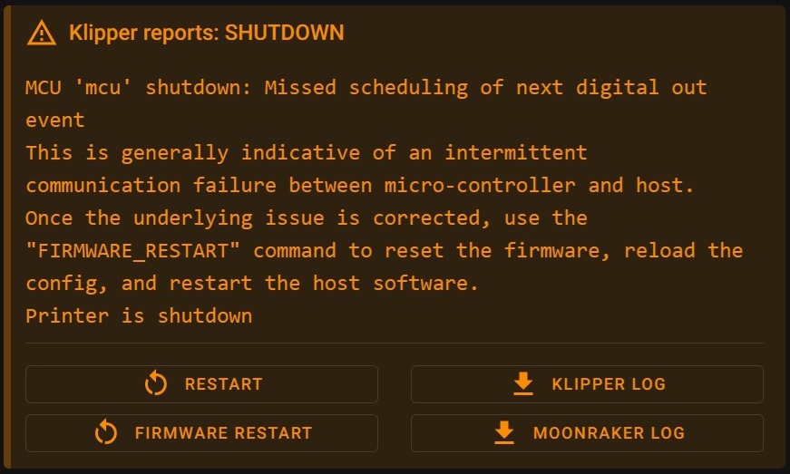
Timer too close

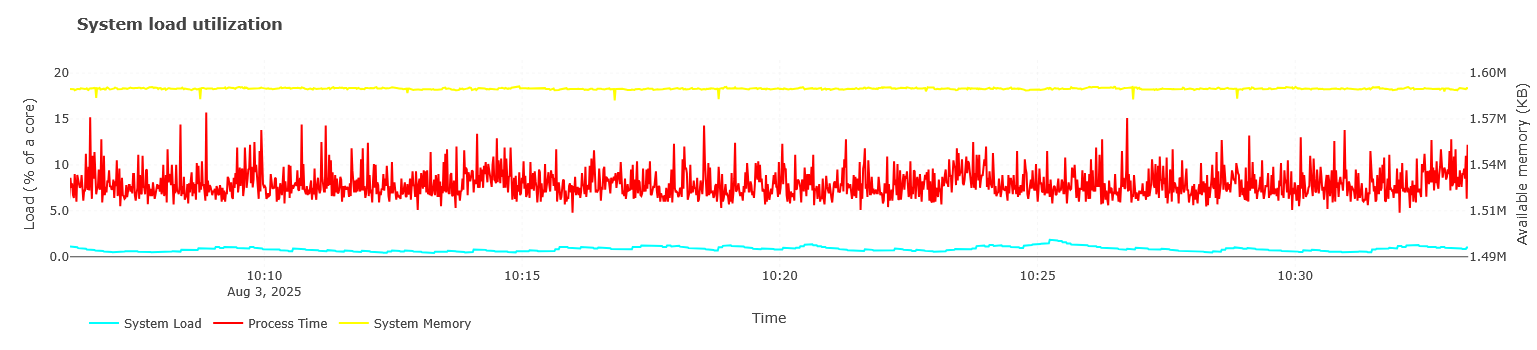
1- High CPU or system load on the host - CPU utilization on the host is less than 50% so I don’t think this applies, but please correct me if I’m wrong.

2-High disk activity or SD card issues - The OS is installed on the eMMC. I don’t have read/write stats on it’s usage, but again I don’t think this applies but correct me if I’m wrong.

3-Memory swapping due to low free RAM - Similar to issue #1, utilization is less than 50% so I’m assuming this isn’t an issue. Again, please correct me if I’m wrong.

4-Overheating and CPU throttling - Just like the previous issues, I’m not seeing any overheating on the M8P. It’s in a separate enclosure with forced air cooling that is separate from the printer enclosure. From what I see temps never get above 60c. The EBB board is in a 50c enclosure so it will be “hot” but since it’s not involved in this error it should be able to be discounted.

5-Undervoltage conditions - No under volt messages are present.

6-USB, UART, or CAN wiring faults-Since this branch of the CAN network consists of the USB connection between the CB2 and the M8P any wiring fault would be a hardware fault on either/both boards. This is unrealistic for me to troubleshoot and since they are installed in an enclosure and stable, flexing from thermal expansion would be the only cause of an intermittent fault. This is a possibility but there is no correlation between load/temps and the errors.

7-ElectroMagnetic Interference (EMI) - Again, a possibility, but since the boards are in a grounded enclosure separate from the PSU and at least 2m away from any other machinery, the boards themselves would need to be the ones putting out the EMI. Which would indicate a much more severe defect than a broken trace/pin. Again, please correct me if I’m wrong. None of the other equipment in the room was powered on when the error occurred.

8-Conflicting USB devices (e.g. webcams, displays, hubs) There is a USB camera and a touch display connected to the board via USB/HDMI. The error has occurred when there was no USB devices connected. I’m happy to disconnect the camera and/or the touchscreen and let the error happen again to prove if necessary. This is another possibility, but the error has occurred with and without these devices connected, so I’m skeptical at best this is the root cause.

9-Incorrect firmware Clock Reference setting - The devices are working correctly normally. An incorrect clock reference would not function at all.

10-Running Klipper inside a Virtual Machine (VM) - NA

11-Poorly written macros or command spam from slicers - no special macro are used that could possibly cause this. Errors happen with files that also print successfully. Errors happen with small and large prints, there is nothing consistent about gcode files that causes the error. Files from multiple slicers have caused the error.

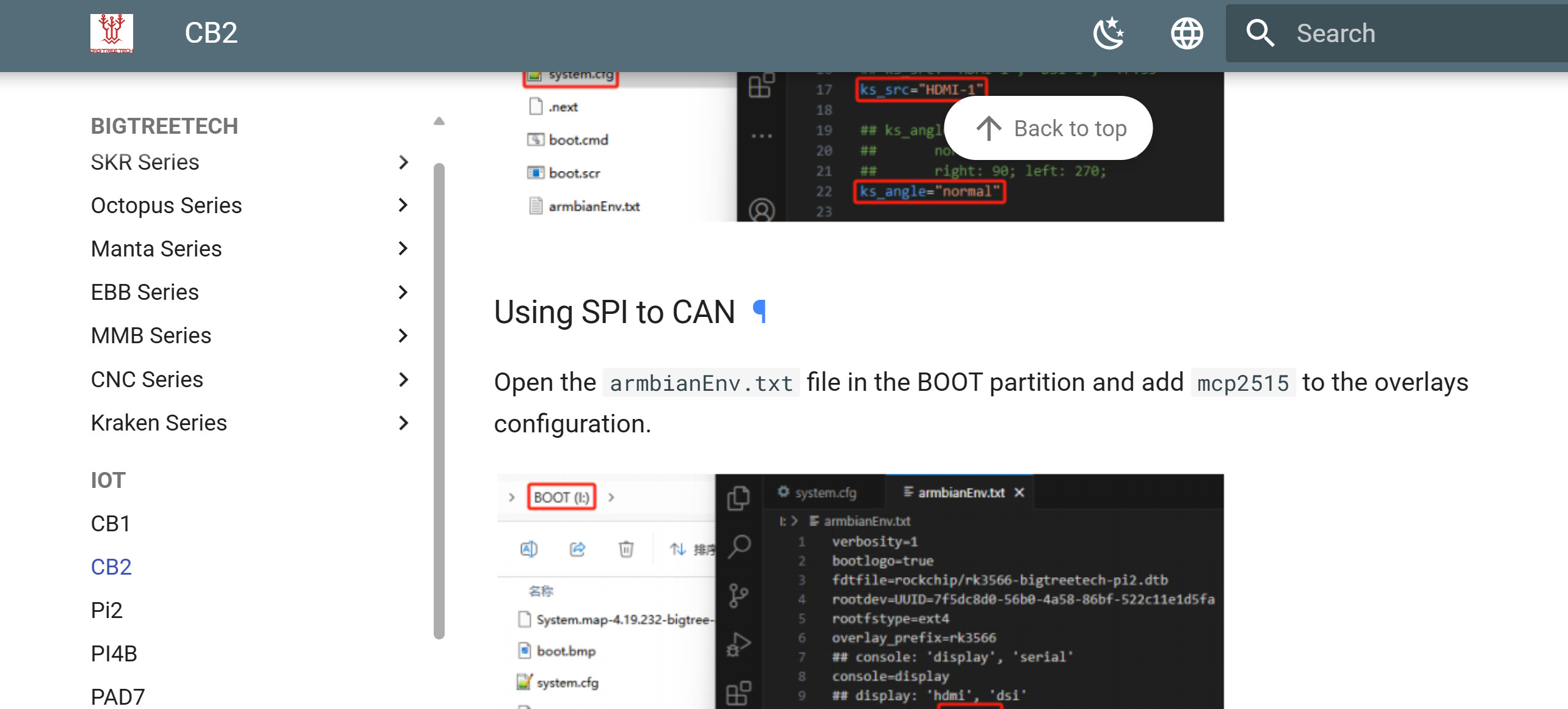
12-Unofficial modules or patched Klipper forks - The CB2 requires the BTT fork. This is my guess at the root cause. I have another CM4 coming, hopefully soon, to try an official klipper installation.

If there is something else in that post I’m missing, please enlighten me.

Reiteration of the error as I understand:

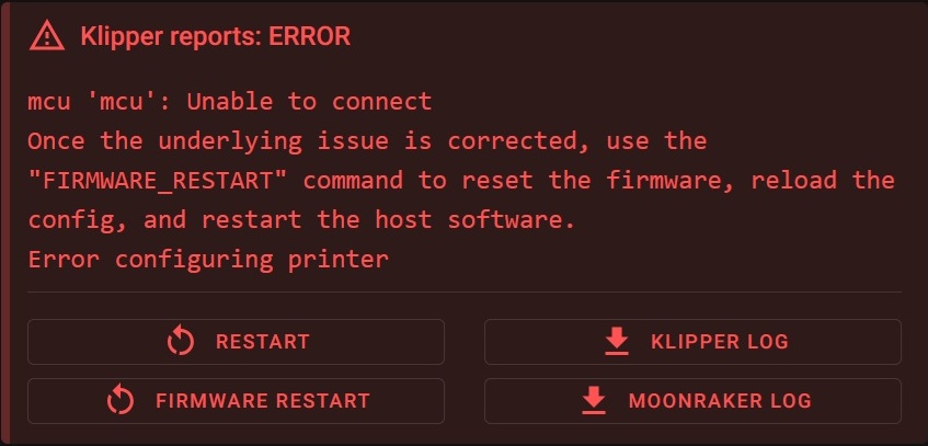
Klipper was expecting a response from the M8P. Sometime between line #51702 and #51703 in the log the M8P stops communicating and the re-transmits start to build up. At line #51705 klipper’s timout has been reached and it reports the failure to communicate with the M8P. Based on these observations, the assumption is that the M8P has failed in a way that it completely stops communicating. When the host is rebooted any messages sent to the M8P to establish a connection are left with no response. The only way to break the M8P out of whatever state it’s in is to power cycle it, forcing it to reboot.

To troubleshoot this I will need to determine what’s happening to the M8P that causes it to stop communicating with the host. I have attempted to answer everyone’s questions and work up to where we are. I was aware going into this that something was causing the M8P to “lock up” and stop responding.

I did not come here before troubleshooting things myself. Knowing that I would need to calm the claims about my wiring to the EBB I ensured that there were absolutely no issues with the rest of the CAN network. The firmware is fully updated to Version: v0.13.0-190-g5eb07966b.

@mykepredko I’m not sure what you’re seeing in the log with that spike. I don’t see that at all even when I zoom in on that section.

To run through the rest of your questions/concers:

Maybe you’ve added hardware to your host like cameras that could be causing a problem, we don’t have visibility to that – There is a USB webcam and a USB touchscreen connected currently. This error has occurred in the past with none of those devices attached. I’m more than happy to remove them and wait for the error to happen again, then post the logs again.

You aren’t forthcoming about your wiring; if you can’t share that information because of an NDA then that sounds fishy to me as you’re doing something unusual – I have tried to be completely forthcoming about the setup and the specifics down to gauge sizes of the individual conductors. If you need me to post it again, I’m happy to but I fully described the harness both to @cardoc and again to @Sineos. The NDA covers publicly posting pictures of hardware. I don’t personally think there is anything proprietary about the cables, but I don’t decide what’s covered in the NDA. The only reason I can think that a picture of the physical cabling is needed is that you don’t believe my statements about it. Never mind the fact that this error has NOTHING to do with the CAN wiring harness connecting the M8P to the EBB.

There doesn’t seem to be any experimentation done to characterize the problem.
You have pointed to the error message but I haven’t seen any work done to try and reproduce the error or make it occur sooner - years ago when I was doing failure analysis on product we’d call this “shortening the ‘scope loop”. – I have done 6 months of troubleshooting and testing. I have eliminated dozens of errors and issues that have cropped up, some blocking, some minor. This error occurs completely randomly. I am unable to cause it to happen more or less frequently. It will usually happen once in approximately 100-150 hours of printing. It usually happens with longer prints, but has happened during the first 5 minutes of a print. My conversations so far seem to be focused on getting people to accept that I have already done extensive troubleshooting and testing. If you have a specific suggestion on how to “shorten the scope loop” I’d love to hear it. That is after all, why I’m here.

Swapping out parts.
You keep going back to the CB1/M8P interface (because of the error message, to be fair) but the 100pin connector interface and USB Hub circuitry is remarkably robust and I don’t think I’ve ever seen a problem here. If I were in your situation and I was suspicious of the interface, I’d swap out the CB2, run tests with the new Host and, if there was still a problem, then I’d swap out the M8P and, if there were still problems: I’D LOOK ELSEWHERE. – I’m trying to find the “ELSEWHERE” to look. We have swapped out the M8P, EBB, and the CB2 with no resolution.

Less talk, more action. As I said above, there is more than 40 posts in this thread and I don’t see any experiments done to try and understand the problem.
When I have a problem to solve my approach is to hypothesize as to the causes - we’re helping with that but, due to the lack of understanding of your system, there’s only so much we can do.
Make up a list of the components in your system and look to see where there could be a problem and test it out. Make that component fail and see if it replicates your error. If it does, publish the results so we can comment and make suggestions. – I have thus far been trying to catch everyone else up to where I am with testing this. I’ll gladly do anything that I haven’t done already and post those results. I have been testing this system for months, stressing each component and finding out how it fails, how to fix/mitigate the failure, and repeating. I will post a full schematic when I have a chance to put one together.

Thanks for the suggestion on the klipper versions. I’ll do an update to the latest version and flash over the new versions to the MCUs. The error has occurred when all versions match, again, I’ll repost logs/errors when it happens again.

@cardoc The boards have been disconnected and reconnected multiple times with no noticed reduction on the error.

My mspaint skills leave things to be desired aesthetically, but I think everything is there for the setup. If you require specifics of hardware I’ll have to check on what I’m allowed to say. Currently everything is from the motion system of a stock Anycubic Chiron with a custom hotend driven by an EBB board. The probe connects directly back to the M8P and is powered by 12v from the M8P through it’s own shielded cable. Shielding is grounded only at the M8P side to ensure a single path to ground for both the CAN cable to the EBB and the probe cable. All cabling from the chiron has been replaced with silicone coated copper conductors. Connector pins are soldered to the conductors and covered in shrink wrap where possible. Only the CAN cable is encapsulated.

I just looked up what the latest BTT CB2 would be: It has a 6.1 Kernel variant. Kernel versions prior to 6.6 may cause issues on the CAN side.
Typically when this issue hits home, one would see a rising bytes_invalid in the log. This seems not to be the case here, but it is worth a try.

Either skip the CB2 and get a RPi CM4 or try building your own Armbian image. According to their commit history, they support the CB2, but do not yet offer an automated build.

Something you could try:

  1. Flash the CM2 with stock image
  2. DO NOT add the CAN overlay
  3. “Make” firmware for MCU using USB communication to host
  4. Edit printer.cfg to find the MCU on USB

You should still be able to use the CAN capabilities of the M8P to communicate to the toolhead with no additional hardware.

My wild theory is that either the MCU or the CPU controls the “clock” for the (pseudo) CAN bus and occasionally some other periodic signal on either board is temporally “lining up” and injecting enough noise to take down the bus. It’s far fetched, true, but none of the obvious theories have solved your issue.

I have another model of CM4 on order. We aren’t willing to assume the risk of our own image.

Anyway you can think of to troubleshoot the M8P in the meantime?

We’ve flashed the same katapult/klipper versions from scratch onto a set of components. They’re scheduled to be swapped in at the next round of calibrations this weekend. We have it set up with nothing connected but a spare toolhead in a vice at a soldering station. It’s running with the CANBUS capture recording and a script that records 600 second blocks and deletes all but the previous block as they’re created. There’s a ~1.5 second gap in the recordings and the extra overhead on the system from the script, especially the eMMC, but I can’t see that invalidating anything we get from it. This is more to fill the time waiting on hardware than in any real hope of a resolution.

@cardoc This may help answer your hypothesis as well. Reading some documentation on the USB CANBUS bridge thing quickly, it kinda looks like it’s CAN traffic inside the payload of frames passed via standard USB between the 2 devices. The firmware emulates the signal from a CAN transceiver to the processor on the designated pins. But that was from a quick read, through 2 or 3 sources, not a full digest of the information. Would love clarification from someone actually knowledgeable. It could also be passing raw CAN data over those lines. I gathered any CAN/USB capable device could be used this way with the right firmware.

I’ll update with anything worthwhile we get from the CAN monitoring.

Well, at least it would be a pointer if it is related to the Kernel or OS, if a recent 6.12 Armbian solves it.

I’m not sure that this is true. I would assume it only works in USB2CAN Bridge mode. Otherwise, it would require its own USB CAN adapter on the board. Since I do not own such a board, this is speculation.

But if the error handling routines in the emulation are the issue, eliminate the emulator. May also actually reduce loads on both the CPU and MCU.

From what I understand it’s one or the other, you can’t use the bridge and connect to the board with USB. I think I remember this causing an issue setting things up at first.

When the new CM4s come in and we put them in the system I’ll load a custom armbian image on a CM2 to test. Will also help to narrow down if it’s the CM2 of the armbian version.

It may if I have time. I could try it without the EBB on a bench when I try a custom armbian build. I can compare utilization between the USB and CAN bridge modes.

CAN is a requirement. This is an extremely simplified setup for testing to isolate this particular bug.

You may be right… Depends on the firmware I guess.

The M8P does have a CAN tranciever (TI SN65HVD1050DR) connected to the MCU on pins PD0 and PD1. I can’t figure out where the data from the compute module arrives at on the MCU.

I’ll say it one last time - it’s a USB connection.

The USB Connection is on the two 100 Pin CM4 connectors and goes directly to the USB Hub (the two red rounded corner rectangles):

From the USB Hub it goes to the MCU (the two green rounded corner rectangles):

Please end this part of the discussion here and now - it’s not SPI, it’s not some custom proprietary interface, it isn’t UART:

On the M#P Boards, the Connection between the CM4 (or equivalent) Host and the board’s MCU is USB

As far as my understanding goes:

  • A CAN node typically (except RP2040) consists of a “CAN aware” MCU (that has CAN function blocks in silicon), a “CAN aware” firmware (e.g. Klipper or Candlelight) and a transceiver chip.
  • If you connect such a combination via USB to Linux, the Kernel integrated gs_usb driver makes the CAN interface available as a networking interface. This is typically done on USB to CAN adapters.
  • If the MCU runs “full Klipper” the setup acts as a “USB to CAN Bridge” fulfilling both the adapter role and Klipper role.
  • You cannot choose if the system acts as the one or the other. So if the Manta boards shall have CAN capabilities, you need to run in “USB to CAN Bridge” mode. This is defined in Klipper’s make menuconfig at compile time.
  • You could compile Klipper for USB only and connect a “standard” USB CAN adapter to the CM board via USB, but this is a different story.

I’ll have this understanding happily corrected if wrong.

1 Like

I’ve (nor @Bacheshatonee) have not recently referred to the connection as SPI since you straightened us out. I apologize for misinterpreting the BTT Documentation. They didn’t use any words I don’t understand but some how I got the wrong idea.

HOWEVER Linux THINKS it is using a CAN bus. Is it not possible that some flaw in the firmware trickery is causing the excessive retransmits that eventually crashes the pseudo CAN data stream.

If not can you propose an experiment that could help isolate this issue?