Fill out above information and in all cases attach yourklippy.logfile. Pasting yourprinter.cfgis not needed
Describe your issue:
I’m trying to install a SHT42 or EBB42 (I have both) through canbus, I got it through USB, but it gave me errors, timeouts,… so I decided to try the connection through CANBUS, with little success if you see my last posts, in a given moment if I managed to see the UUID, but when restarting nothing…
So yesterday I decided to restart the whole process, and document it, so that if you see where the error is, tell me and I can correct it.
I have decided to do it with the combination of UTOC + SHT, but I also have the combination U2C + EBB42, but I can’t make it work either, it happens to me similar
The idea is to do it in 3 parts:
1 - This introduction
2 - UTOC Configuration
3 - SHT42 Configuration
Let us begin…
I’m sorry if I bother you, but I’m a bit desperate and I don’t know what to do…
0 Edited… In web https://canable.io/, flash canales firmware (estable release) in Utoc.
First, the wiring of the UTOC board, it is connected by a 1 m USB cable (it is longer than necessary to be able to do the tests) to rPI, and to the power supply of the PSU…
When connected like this, many lights on the UTOC board come on, as you can see. After this edit the CAN0 file, this
after reboot… to check if it worked, send by SSH, the command…
ip -s link show can0
at that time there is no activity in CAN0, but I think, I am not sure, that it is normal, since I have not yet connected the SHT42
Before starting I have checked the continuity, with everything off, the cable that joins UTOC and SHT, between the 24v pins, groud, H and L…
1 - SSH to Rpi
2 - cd ~/klipper/
3 - make clean
4 - make menuconfig
5 - Select these options:
A- Enable extra low level configuration options
B- Micro controller Architecture (..stm32...)
C- Procesor model (STM32F072)
D- No bootloader
E- Clock Refecnce (8 Mhz...)
F- Comunication Bus (Can Bus PA8/PA9)
G- 250000 Can bus speed
H- GPIO not chequed
6 - Quit, saving changes
7 - Compile firmware: make -j4
8 - Login in RPI FTP, and save file created /klipper/out/klipper.bin in HD
9 - With STM32, burn the firmware created (klipper.bin) in SHT42
9.1 - Place jumper
9.2 - Open CubeProgramer
9.3 - Full chip erase
9.4 - Select file created
9.5 - Start Programing
9.6 - Pop message all ok
9.7 - Disconnect in Cubeprogramer
9.8 - And disconect SHT42 from PC
12 - Retire jumper for programing.
13 - With a multimeter check resistance between, and its 0
14 - Place terminator jumpers, and recheck resistance, and now its 119 Ohm
11 - Conect Utoc to SHT with harness do it… checking 2, 3,… x times. Seems OK
12 - Power on printer… after a seconds too many light power on…
13 - Login SSH in Rpi
14 - Recheck CAN0 its up:
15 - Run UUID script: ~/klippy-env/bin/python ~/klipper/scripts/canbus_query.py can0
16 - After some seconds… 0 uuids found
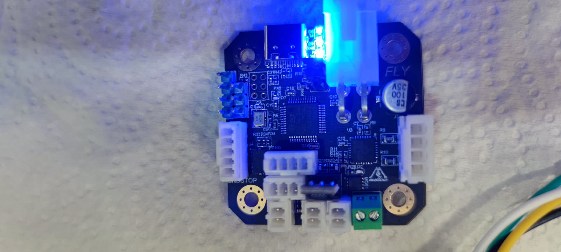
If you see something that is not right, tell me… the only thing I see that is a little suspicious is a mark on the SHT Chip, a point… the board seems to work, it can be connected to STM, it can be update, the lights come on…
FWIW, in my very first response to you probably more than a week ago I recommended that you follow this guide:
Without going through your subsequent posts in detail, it does not appear that you installed the CanBoot bootloader. Once again, please review and follow the above guide.
The truth is that I have lost count of the websites I have looked at. M I also think I remember to install in Utoc the canable firmware. I’ll look at it again in case something goes wrong.
The mark on the chip is normal, that’s no damage.
I too recommend installing CanBoot first… I’ve done it that way and it’s been working great.
Also, on a side note, I highly recommend setting the txqueuelen value to 1024, 128 has a much higher chance of a lost package causing a connection break.
The 120 ohm jumper on the U2C closest to the USB-C is the only jumper that needs to be in place for your setup, remove all others for this board.
The 120 ohm jumper on the EBB needs to be installed, others depend on your devices connected to the EBB. The USB power jumper doesn’t need to be in place if power is provided via CAN bus connector.
On the EBB the connector just below the CAN bus connector is not a jumper it is for continuing the bus to other boards or checking the bus resistors.
Here are diagrams I worked up for the U2C & EBB boards.
I’m guessing that majority of 3D printing enthusiasts would be too young to remember 10BASE2 ethernet or even SCSI. These would have been probably the most common end-user facing interfaces requiring bus termination management, but they have been gone for very many years. I cannot think of any current consumer facing (i.e. non-industrial) bus topology that requires termination management.
I suppose that I have put jumper in 2 shockets… Or only in 1 of them depending on where you have connected the can board…?
The same thing happens in the Utoc?
I recognize that my English is not very good … But the one who has written these manuals, they are not going to give him the Nobel Prize for literature, and that of Bigtreetech, yet, but that of Mellow,… Buff
There are three jumpers on the U2C for termination; only one is needed when one device is connected; if two or more are connected to the U2C, no termination jumper is required.
I understand that you may be struggling with the language. This is also why I keep emphasizing that you follow the link that I shared.
The author provides detailed illustrated information for all steps of the CAN setup process in Klipper - if you follow it you will not need any other information. He describes how to flash & configure USB to CAN adapters with specific examples for different common boards. He also describes how to flash & configure CAN toolboards with specific examples for different common boards. With your setup you need to make sure that you complete these steps:
Connect, configure and verify that your UTOC board functions with the host (Raspberry Pi)
Configure, compile and flash CanBoot boot loader onto the toolboard of your choice (say EBB) from the Pi via USB
Connect the EBB to the CAN bus of the UTOC, making sure UTOC and EBB are both terminated
Configure, compile and flash the EBB with Klipper
Edit your printer.cfg according to your needs & your toolboard (EBB)
All the above steps are covered in the link, with the exception of termination requirements.
One for one USB-A connection and the other for the other USB-A, I posted a link for the information on the U2C V1.0 without USB-A connectors, & V1.1 with USB-A connectors.
Thank you all for your advice and for your patience… it seems that in the end I have succeeded… this would have been impossible without you…
THANK YOU!!!
and… What was the fault?
Well, I want to think that it has not only been a failure, it has been a chain, the main one. That about 2 months ago I changed my Rpi 2, for a new Rpi 4, which seems to be working correctly, but a few days ago I realized that what I connected via USB (memory, keyboard, mouse) sometimes was not detected. …this caused the process to fail. Realizing this, and changing it to the old Rpi v2…, following the steps and putting the jumpers… IT HAS WORKED. That explains that a few weeks ago I gave a false positive, because at that time I momentarily went back to the old Rpi v2… After reading on the internet, I have seen how that USB failure has not been the only one that has happened to it… …
T H A N K S !!!
@NAPCAL You have been very patient with me…!!! @Arakon and @ReXT3D Your advice has helped me get on the road, until, for now, I reach the goal…